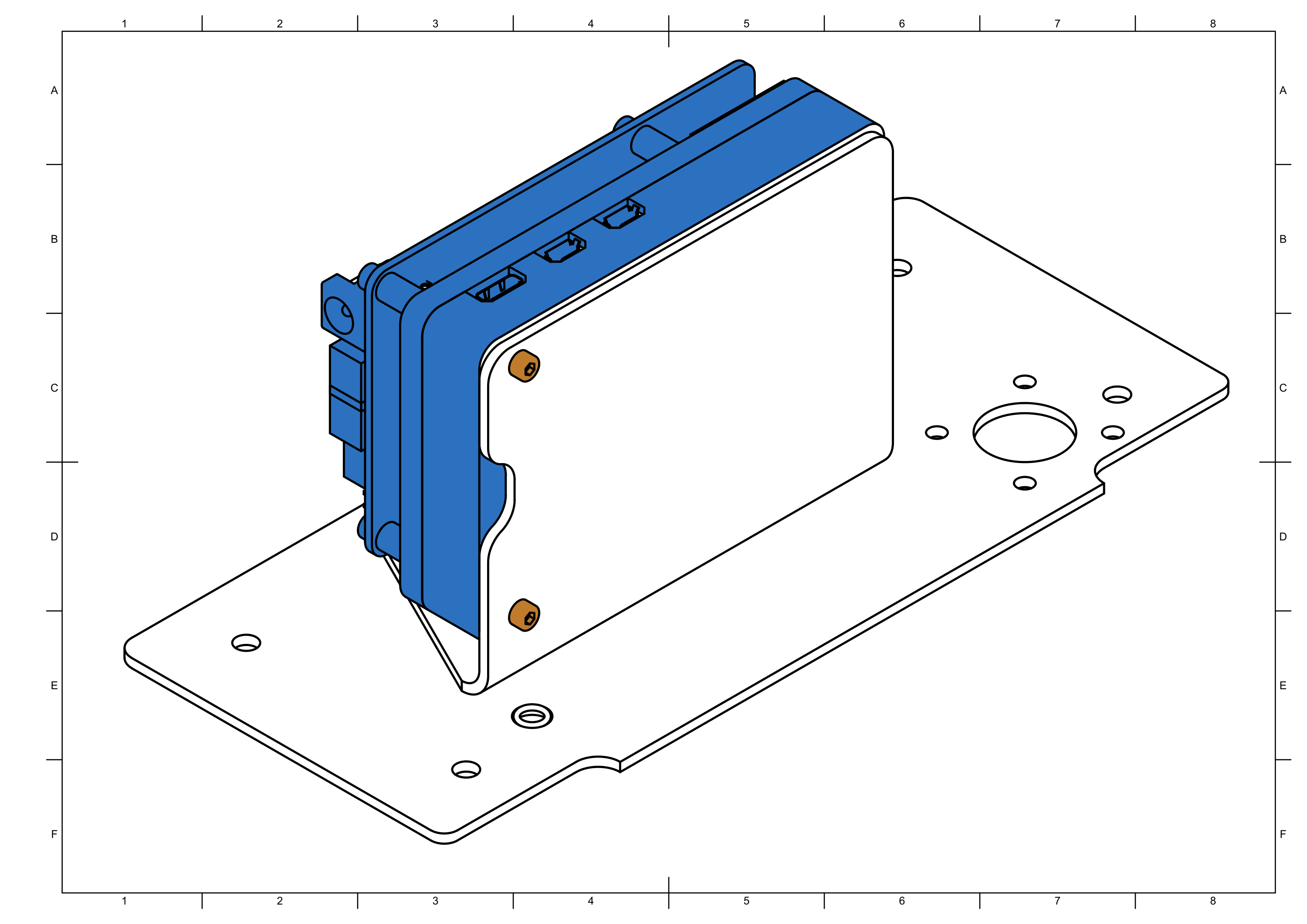
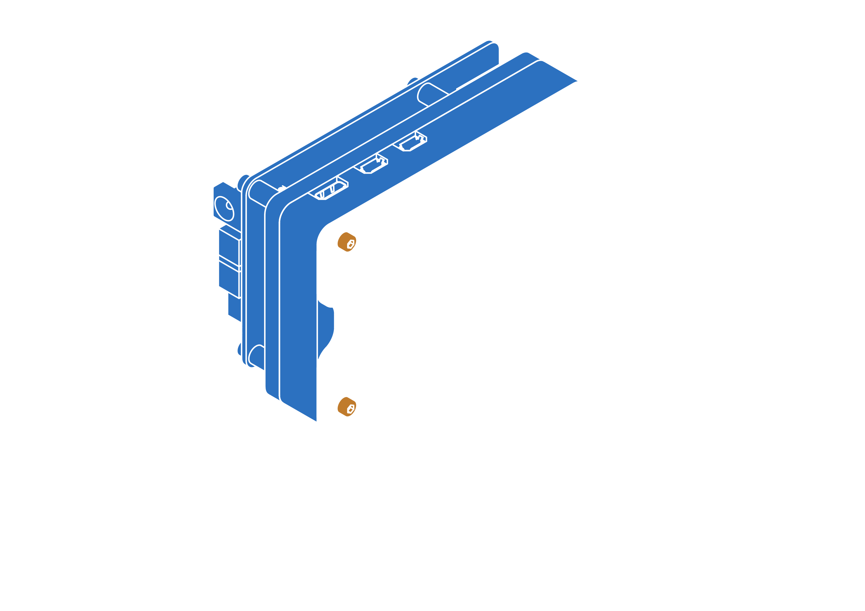
Task 2: Main Electronics Box (MEB)
Assembly time ≈ 60 minutes


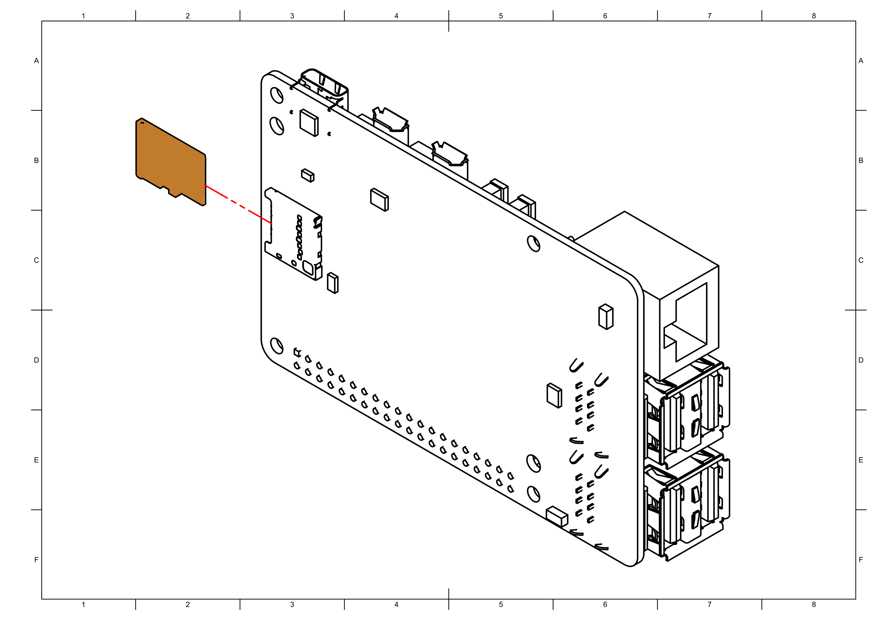
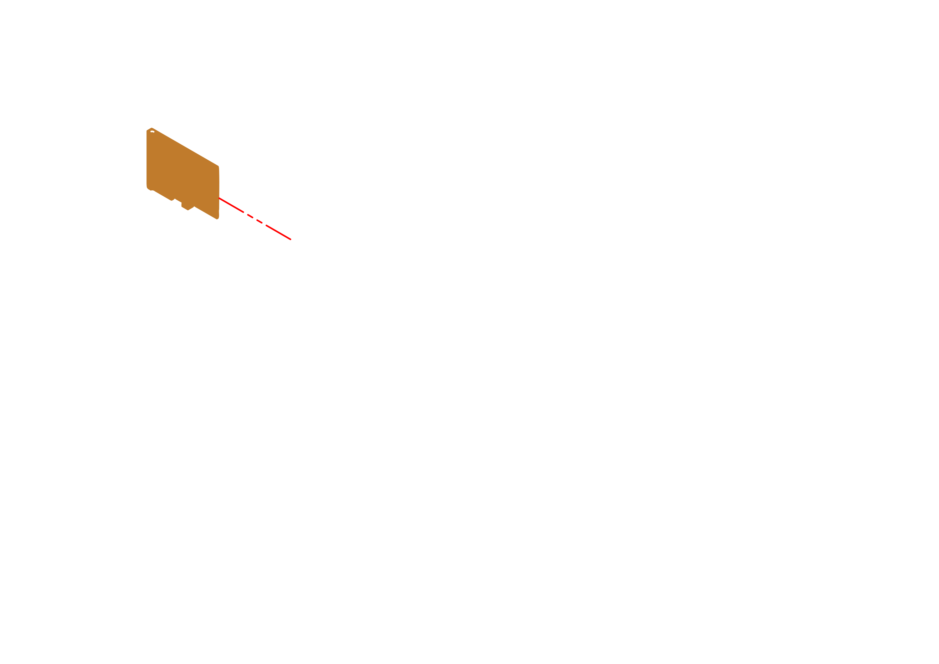
Step 0
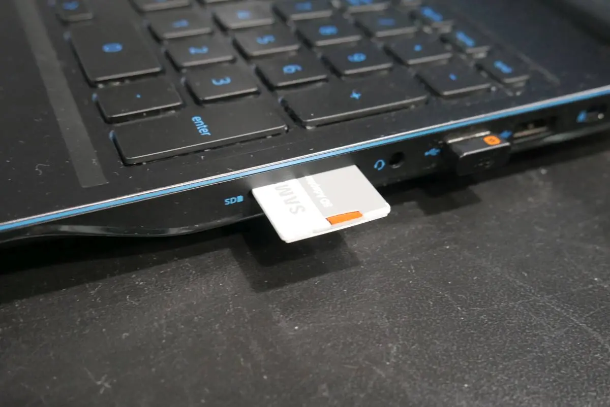
Burn LeoOs image to a microSD card using this tutorial:
📄Software update
A guide to updating your Leo Rover by flashing the latest LeoOS image to a microSD card using tools like Etcher or command-line utilities.
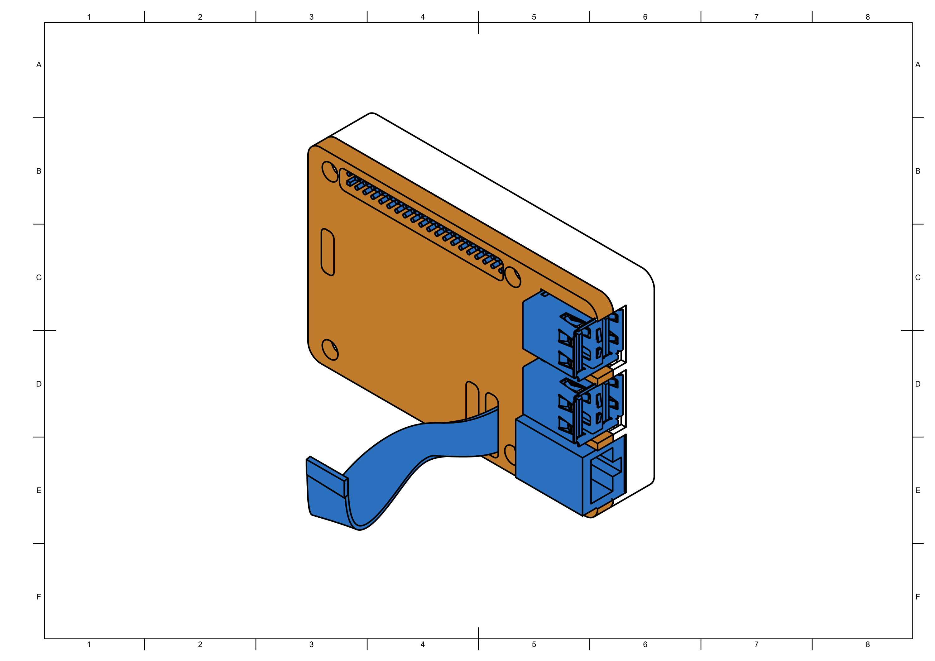
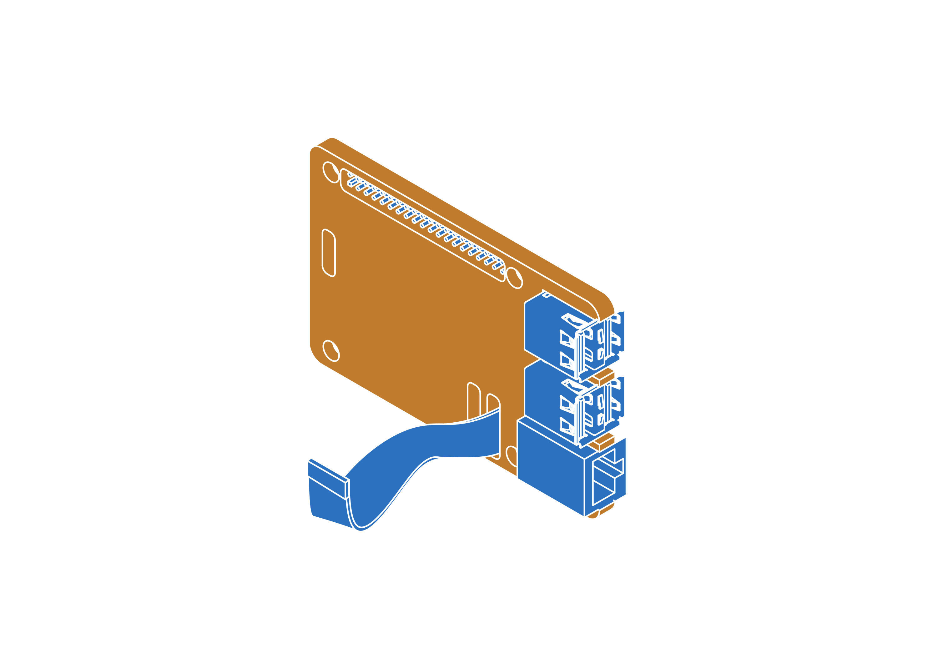
Step 1


Step 2

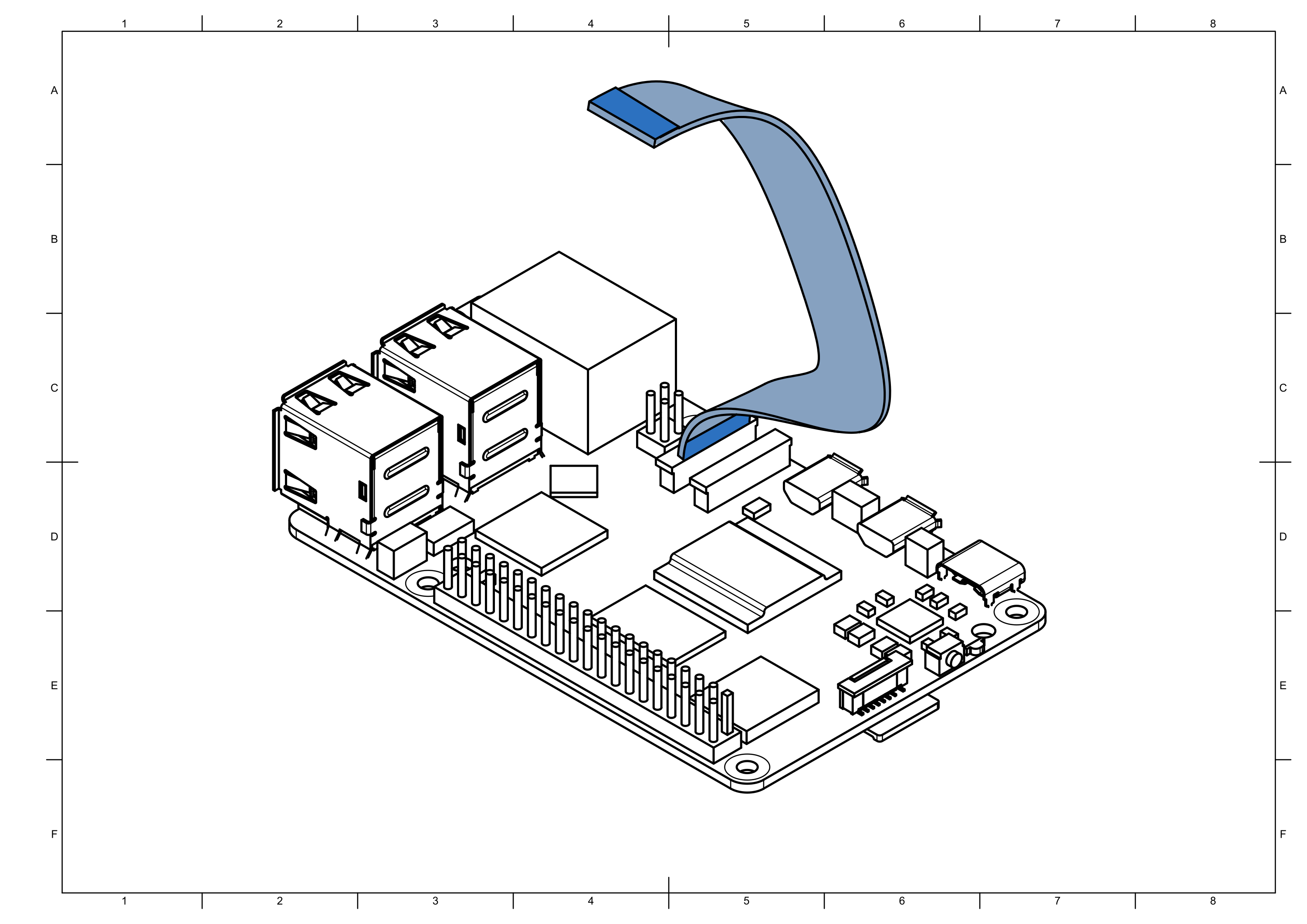
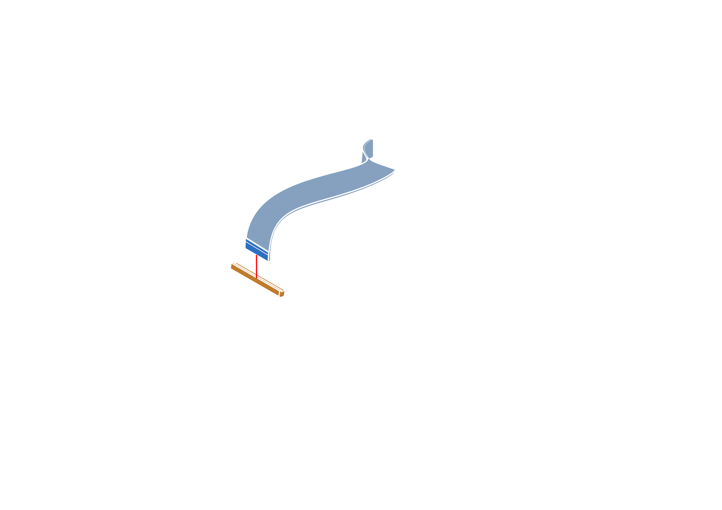
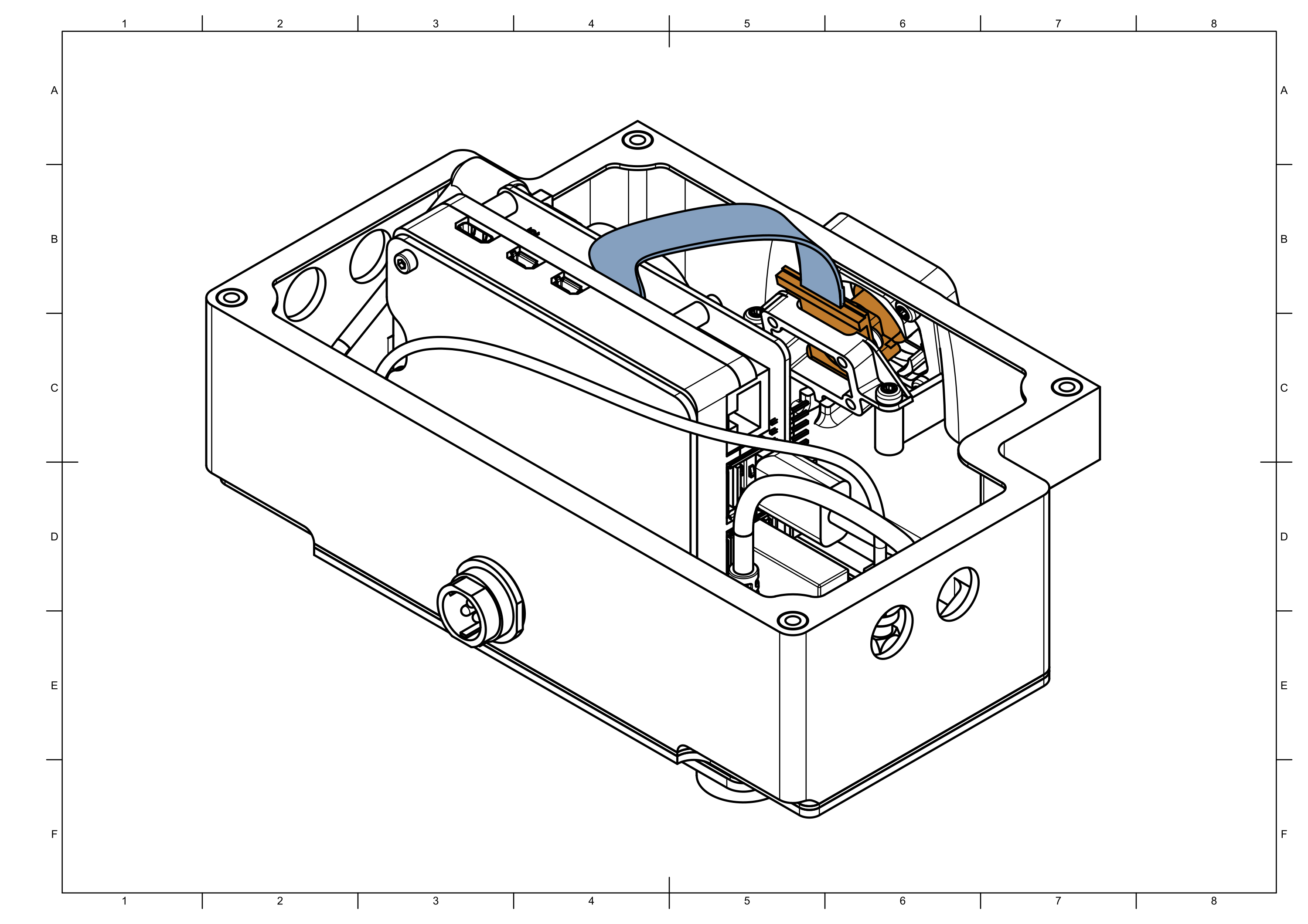
note
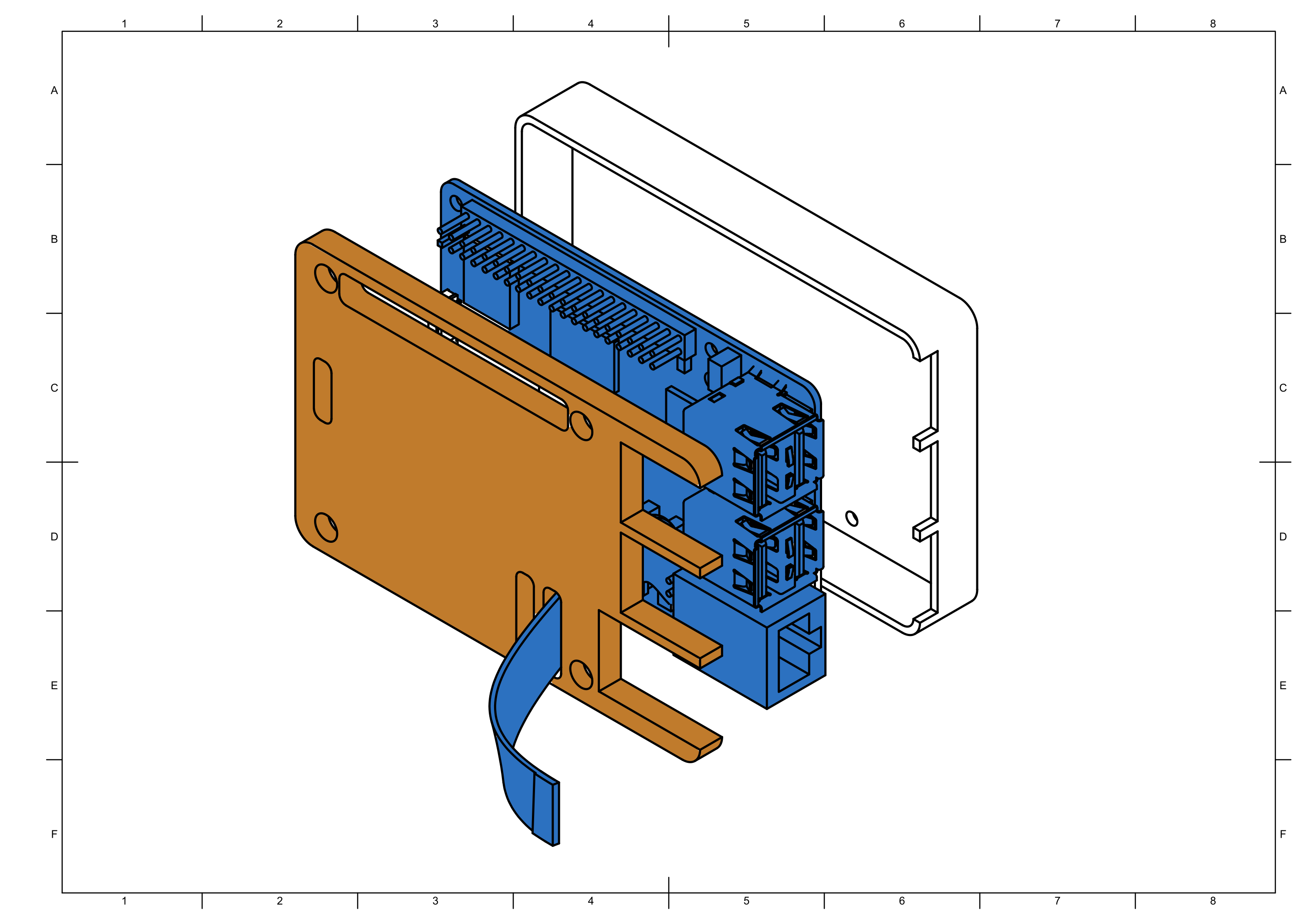
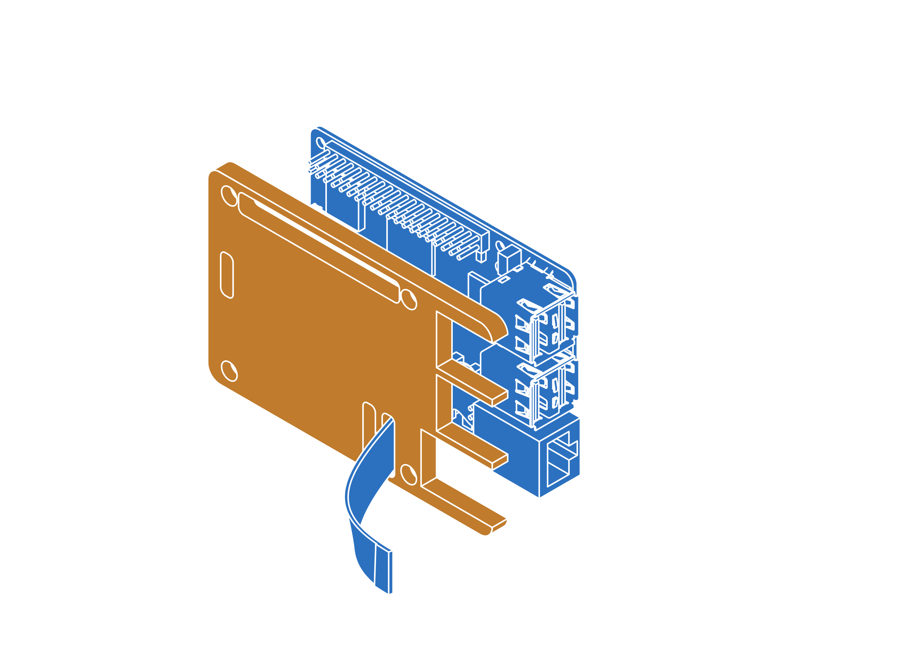
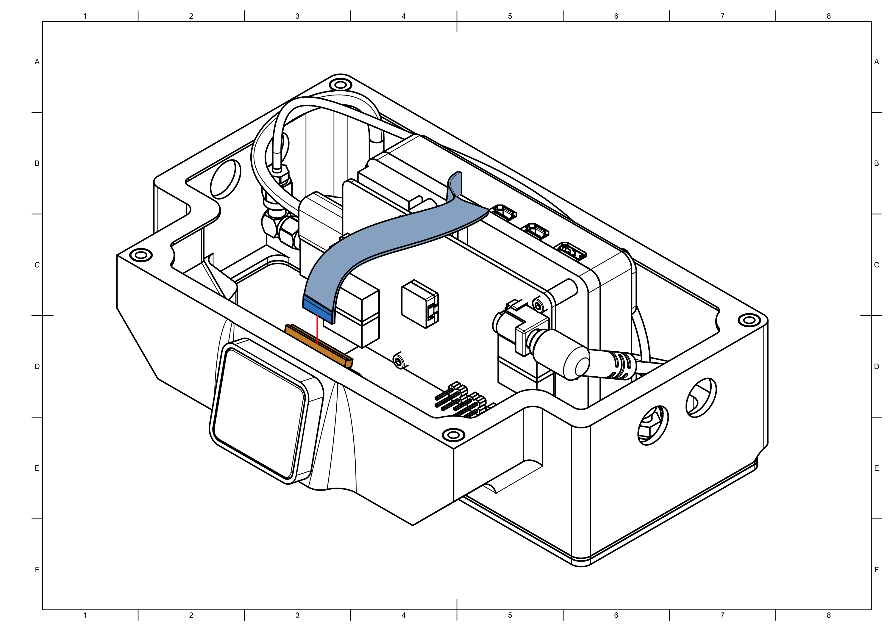
Make sure that camera ribbon is pushed all the way into the CAM0 connector. Lock the ribbon by pushing down on the connector handle.
Step 3


note
Remove tape from heatpads before closing the case.
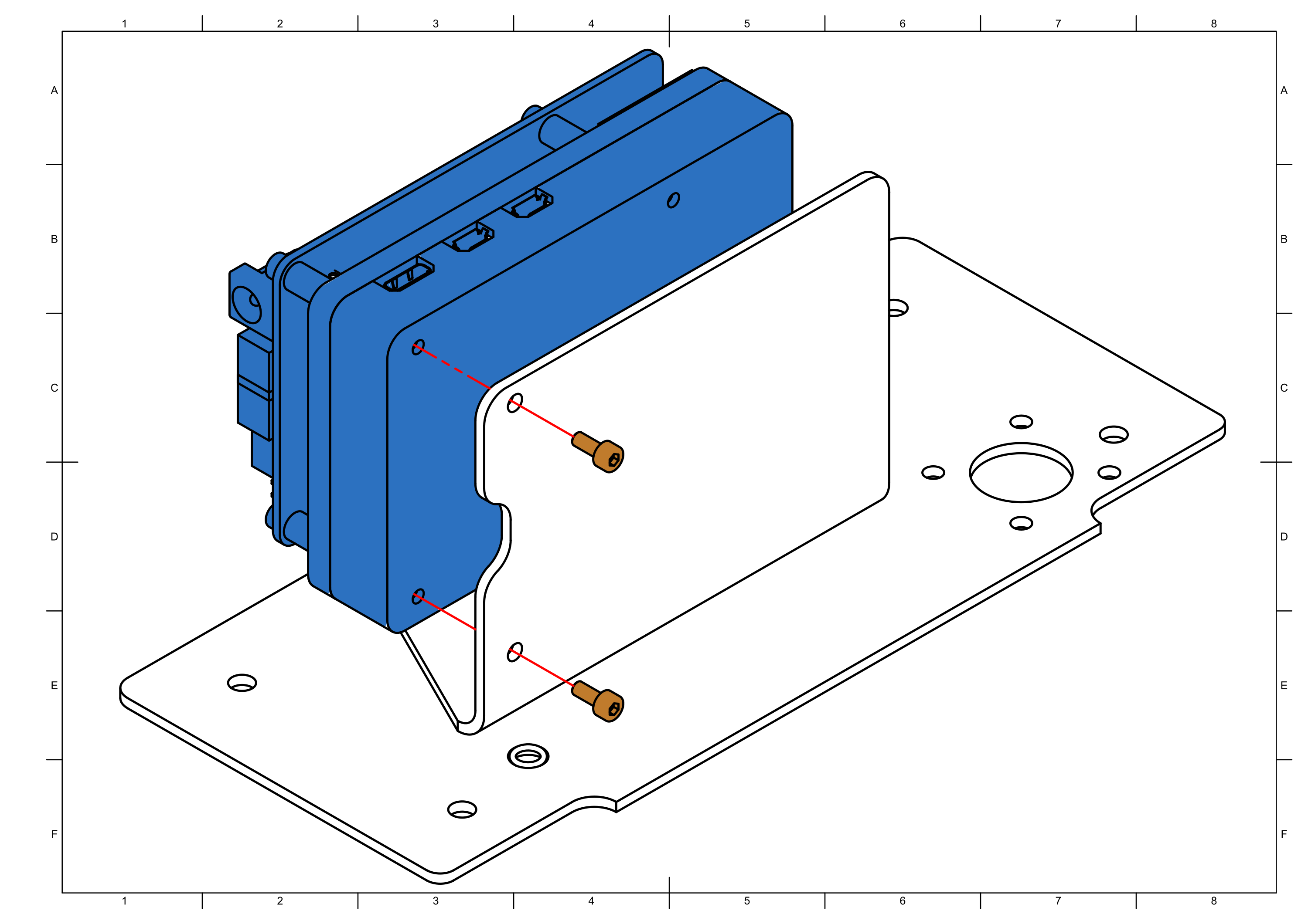
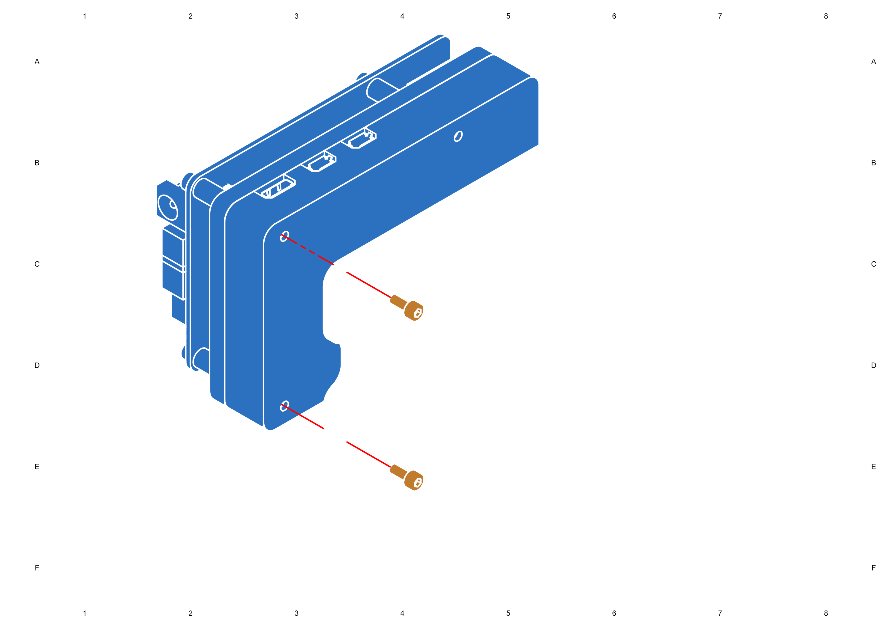
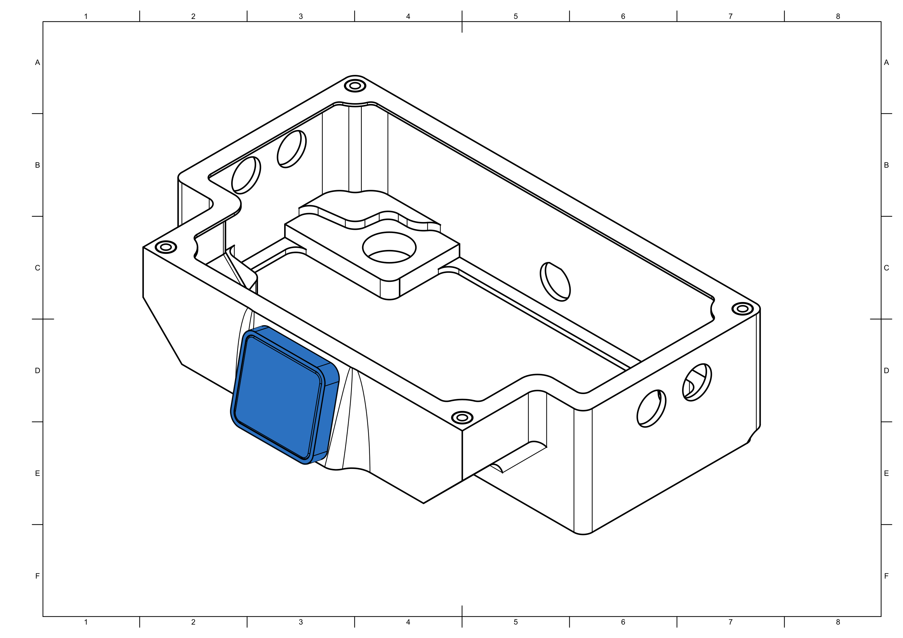
Step 4


Step 5


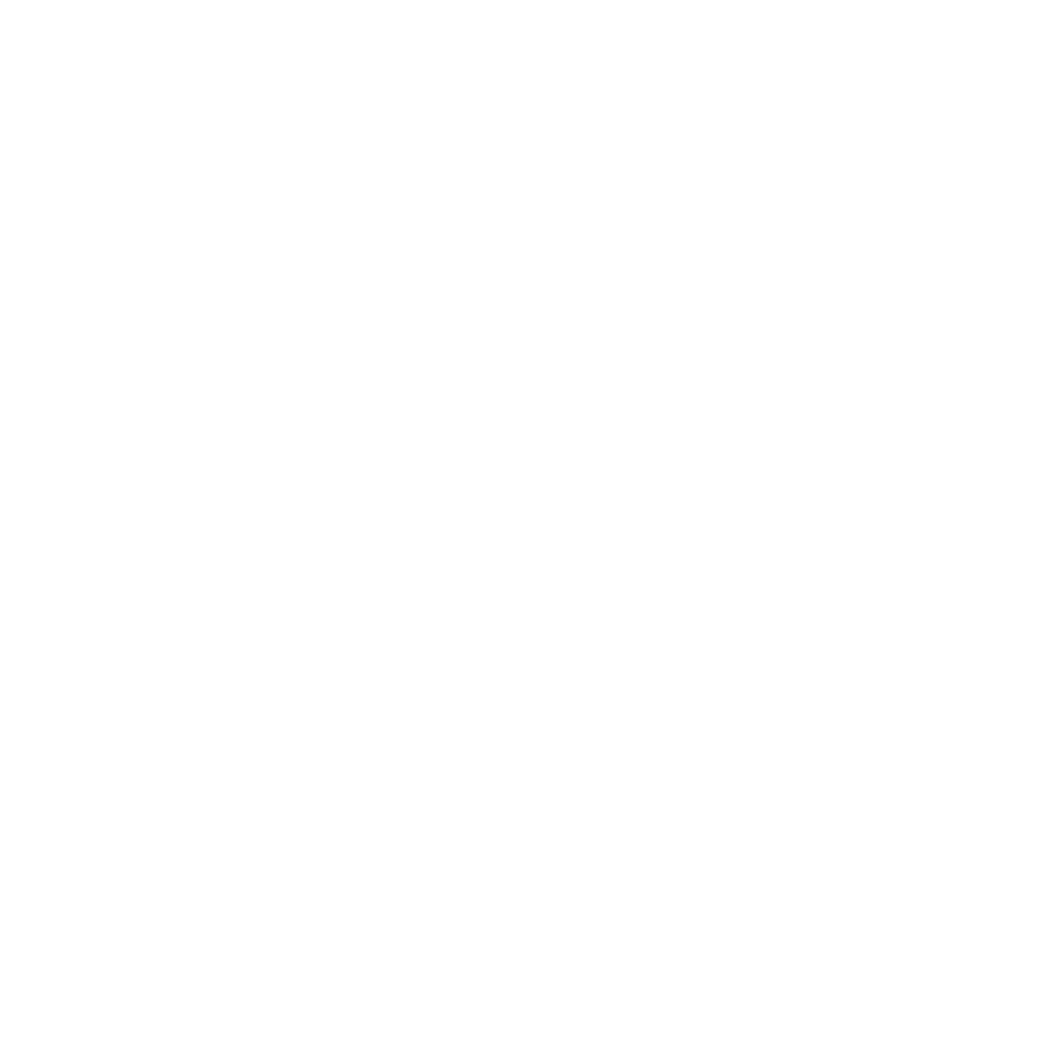
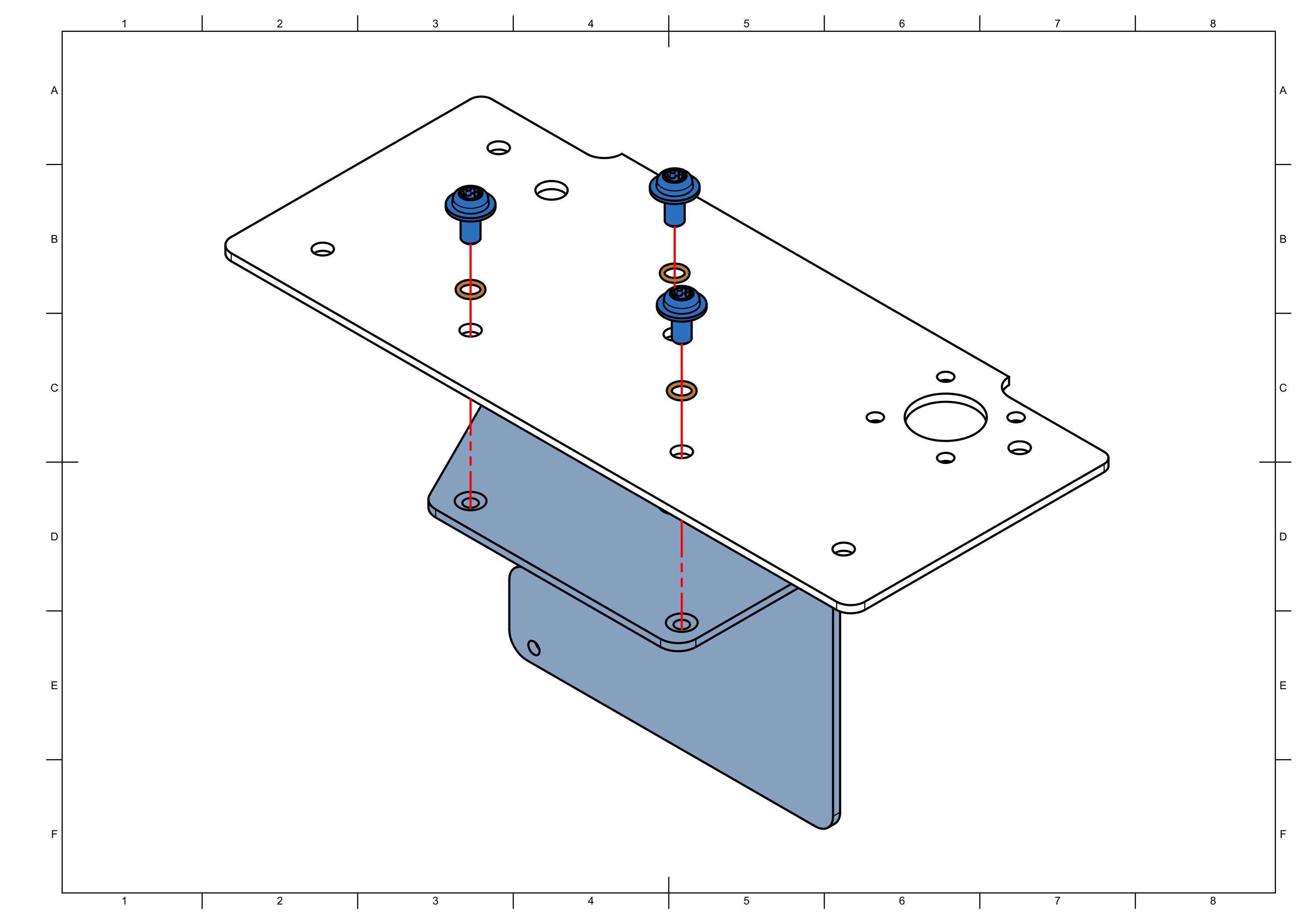
note
Do not overtighten the screws it will destroy the seal.

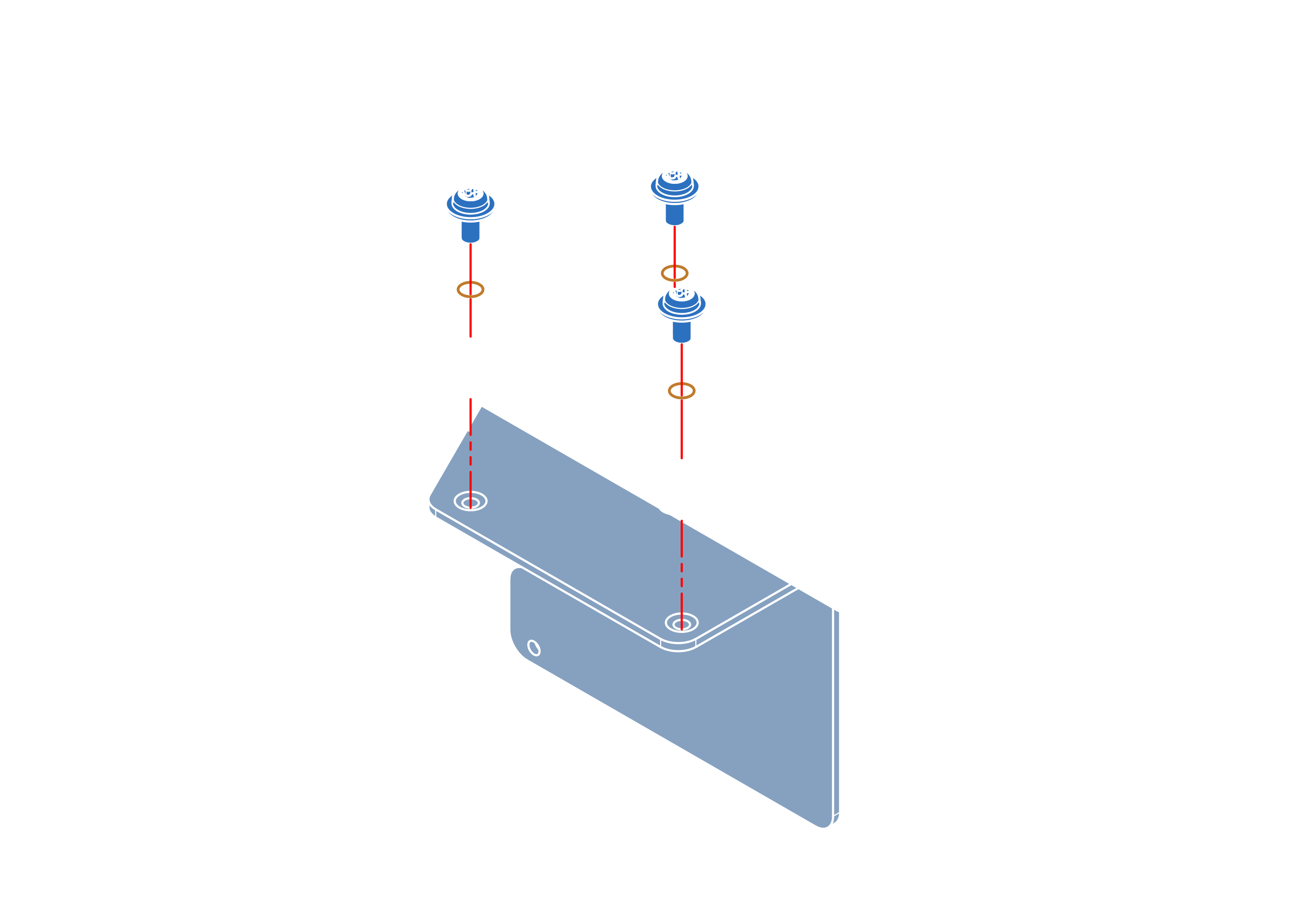
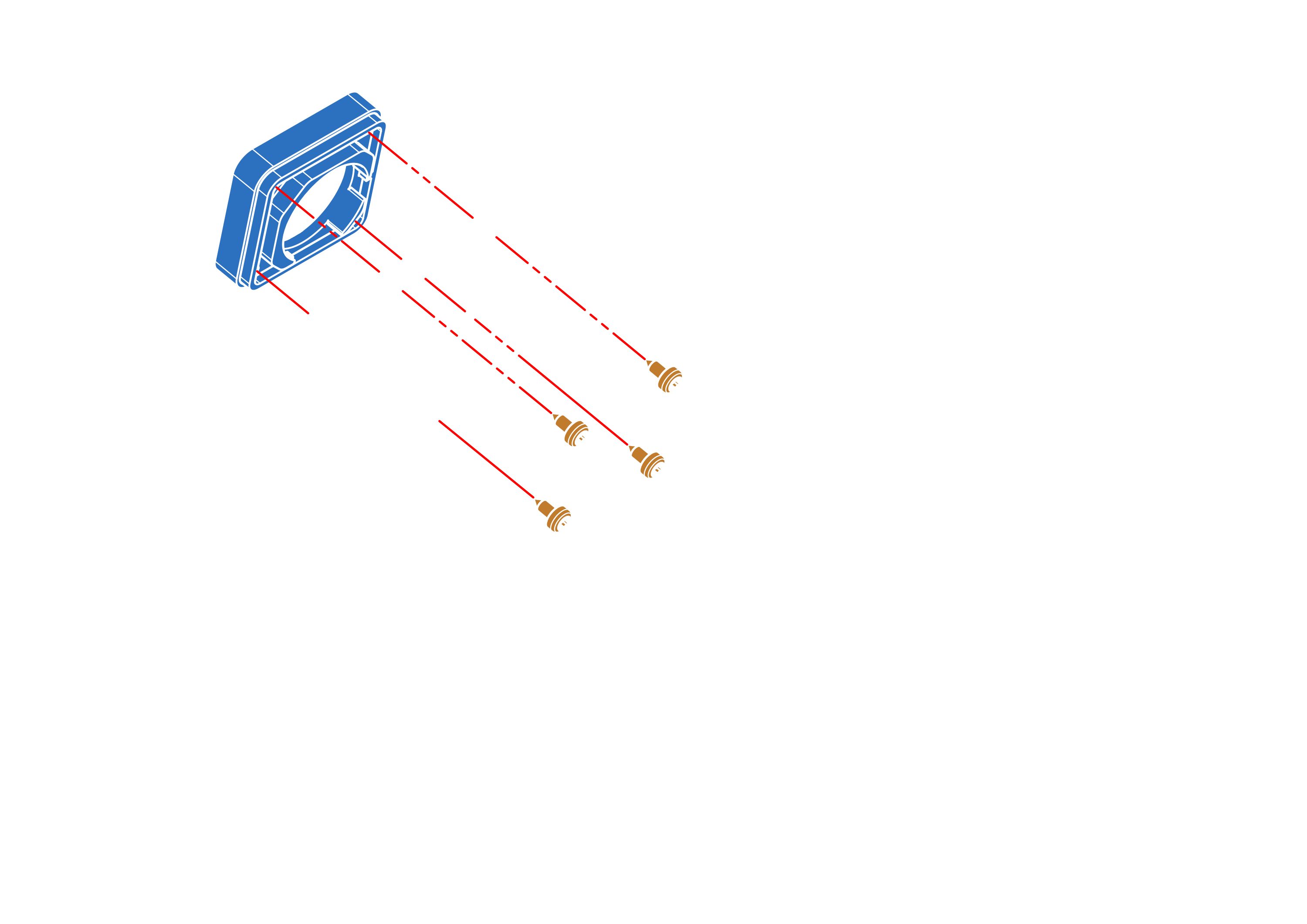
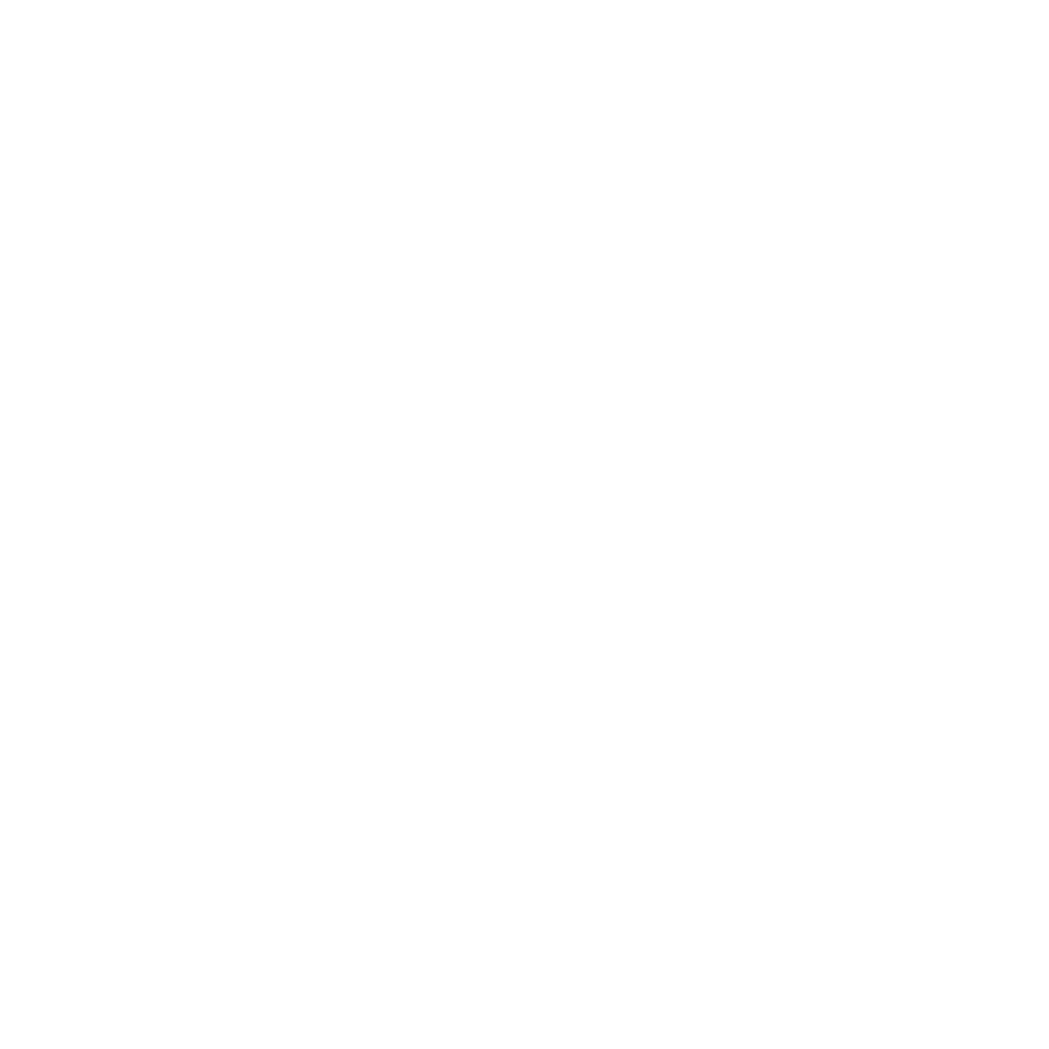
Step 6


Step 7


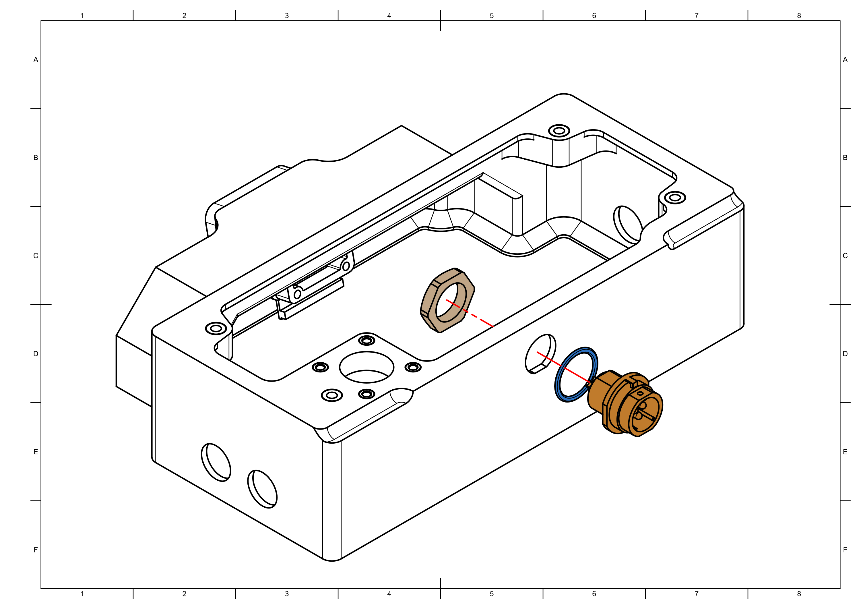
Step 8


note
Do not overtighten as the seal can easily be crushed.
Step 9

Step 10


Step 11

Step 12


Step 13


Step 14


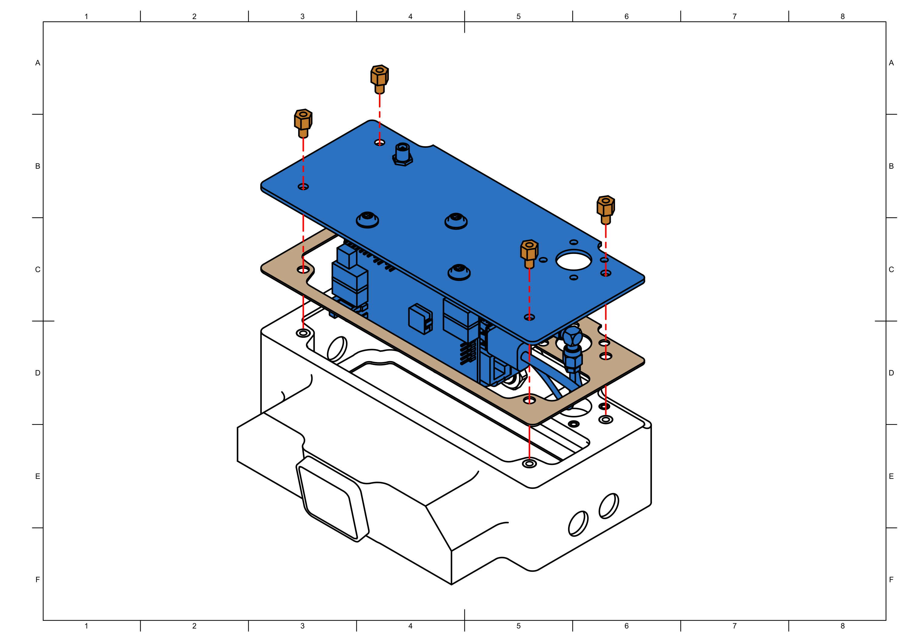
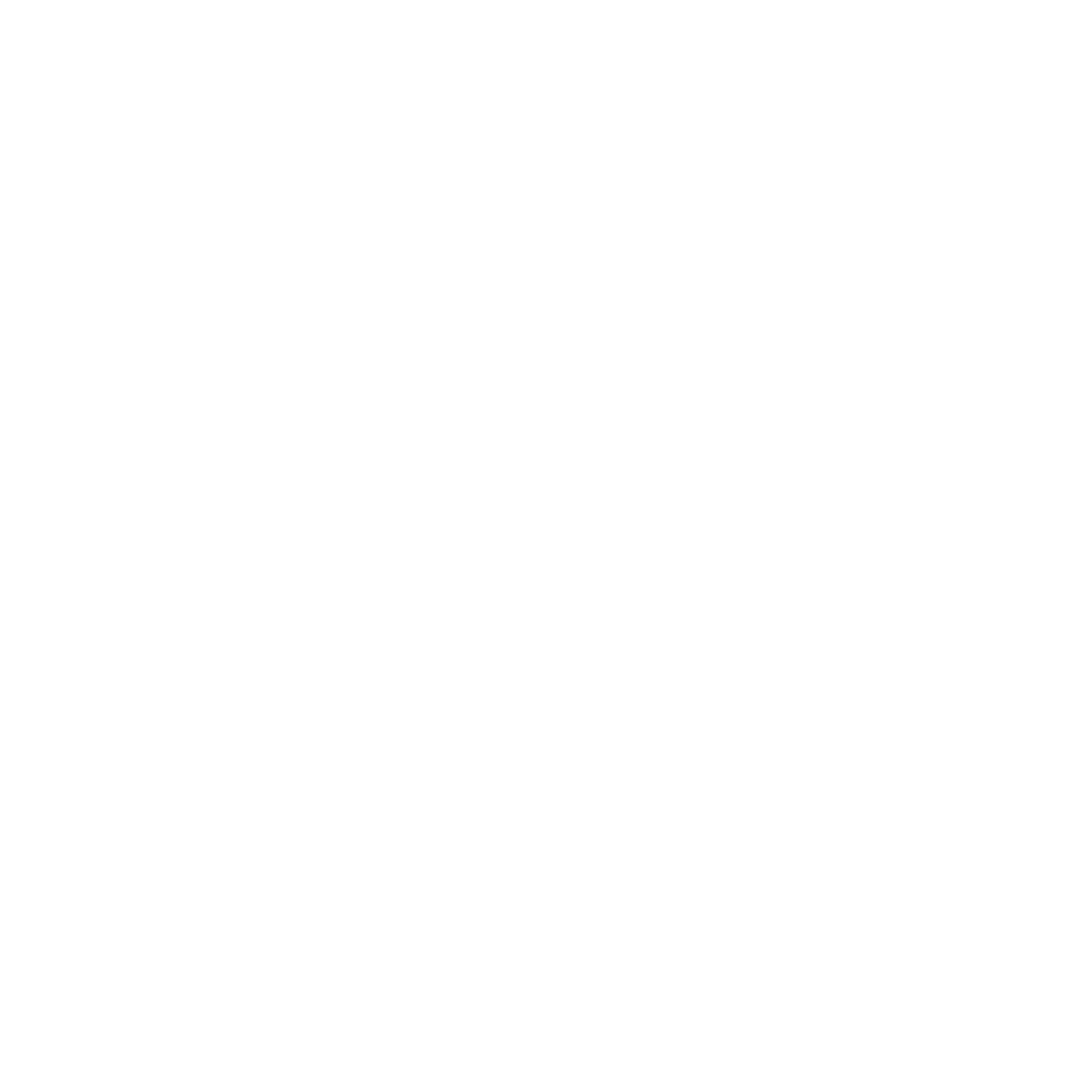
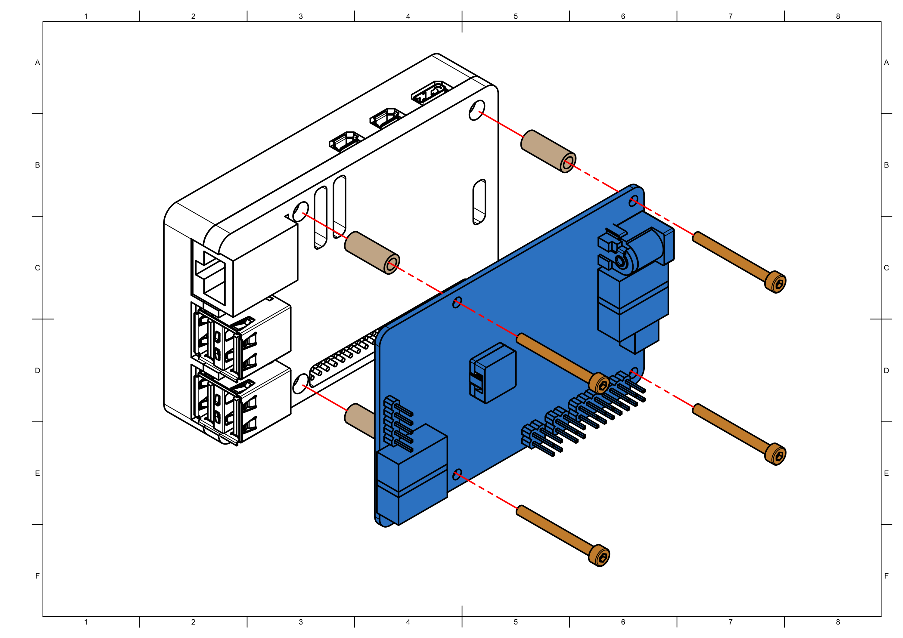
note
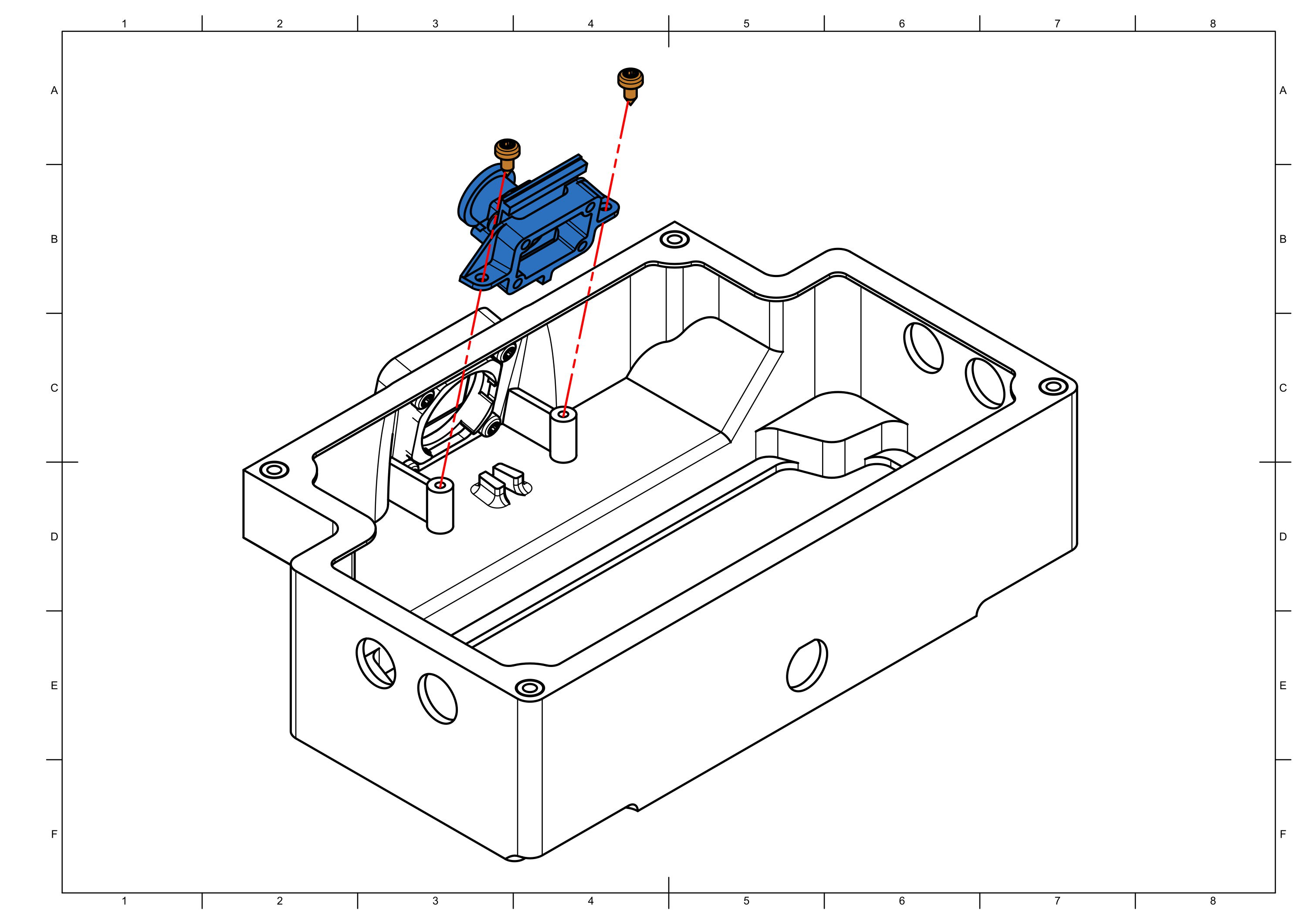
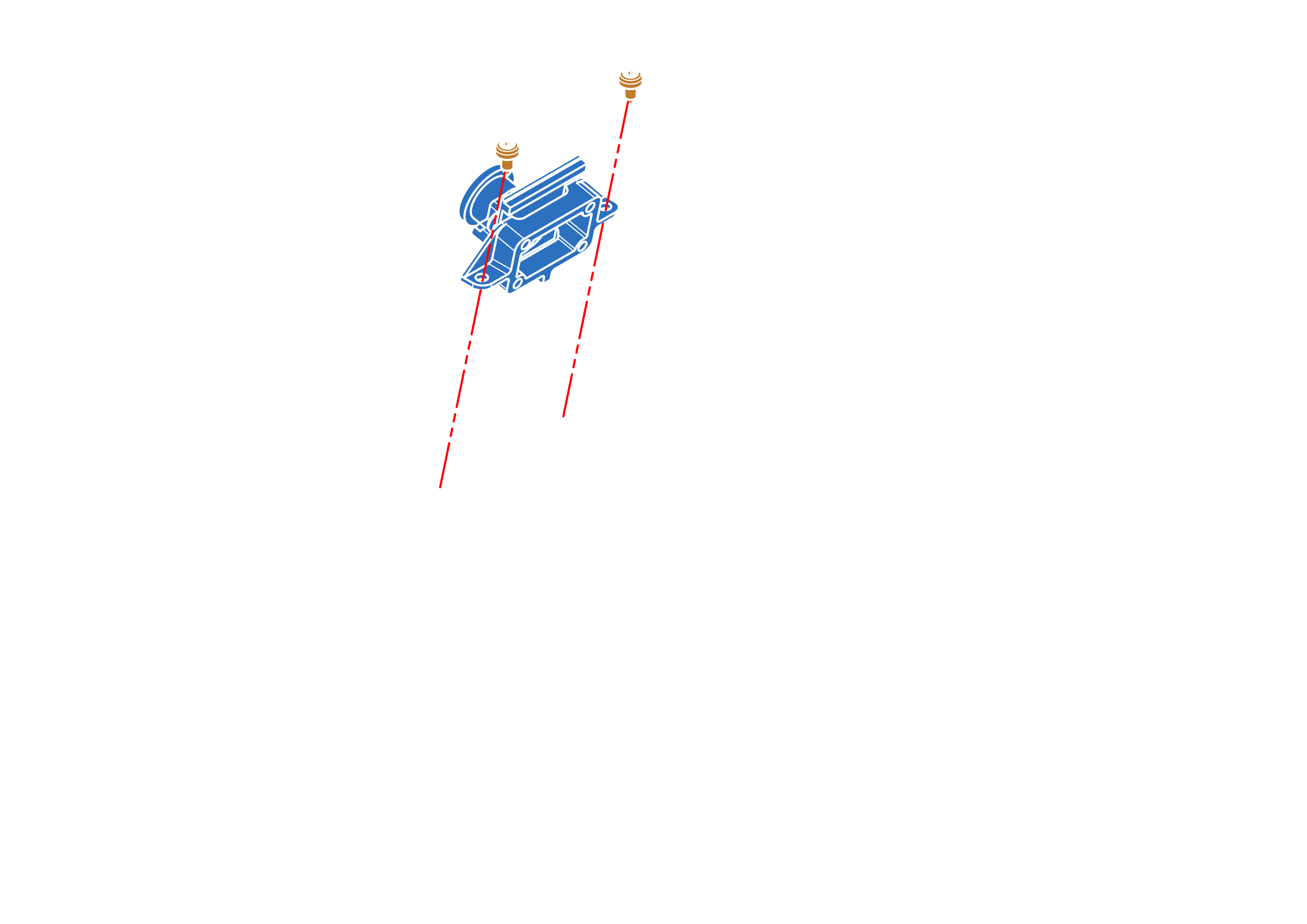
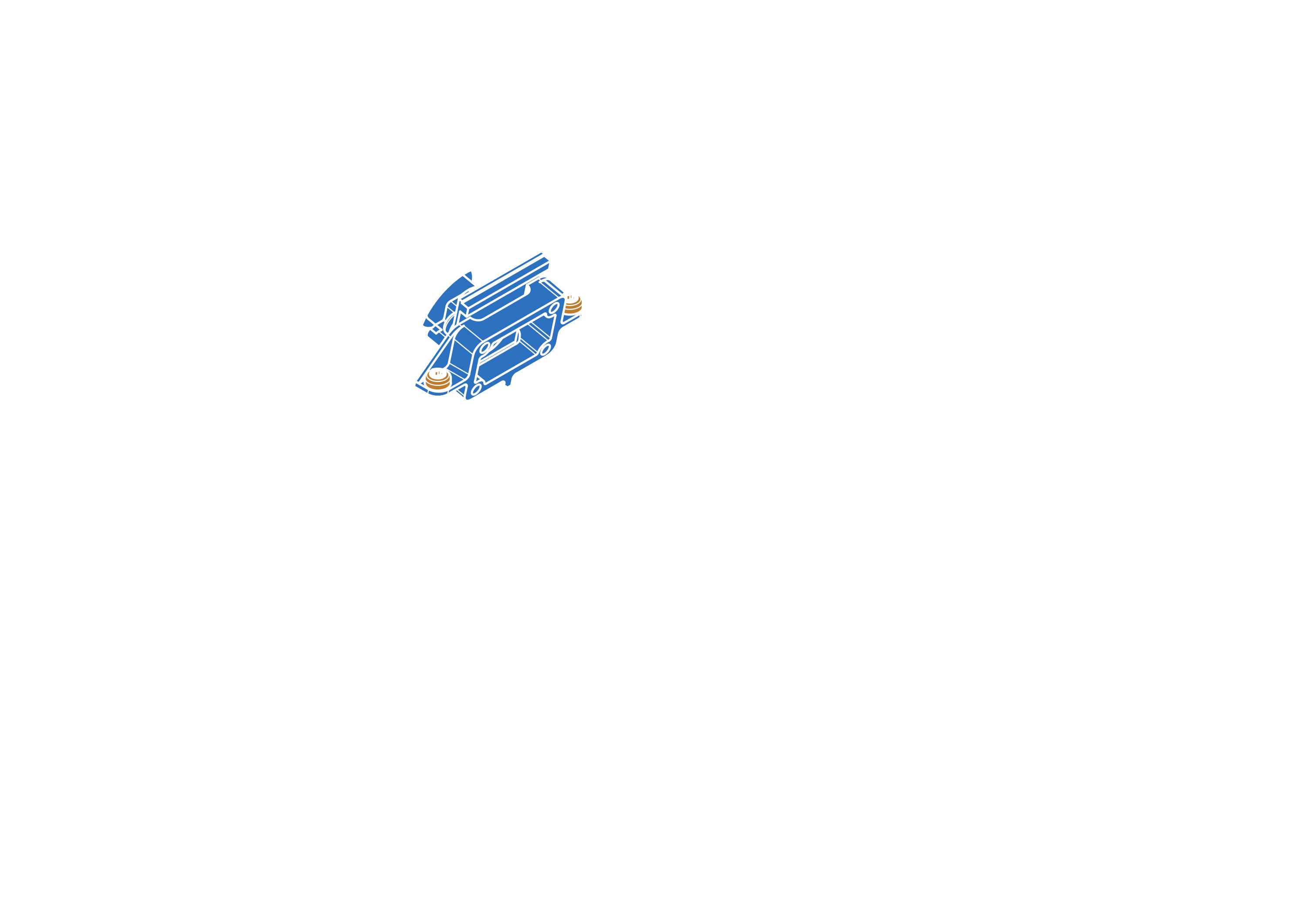
Use loctite on the standoffs to prevent them from loosening over time.
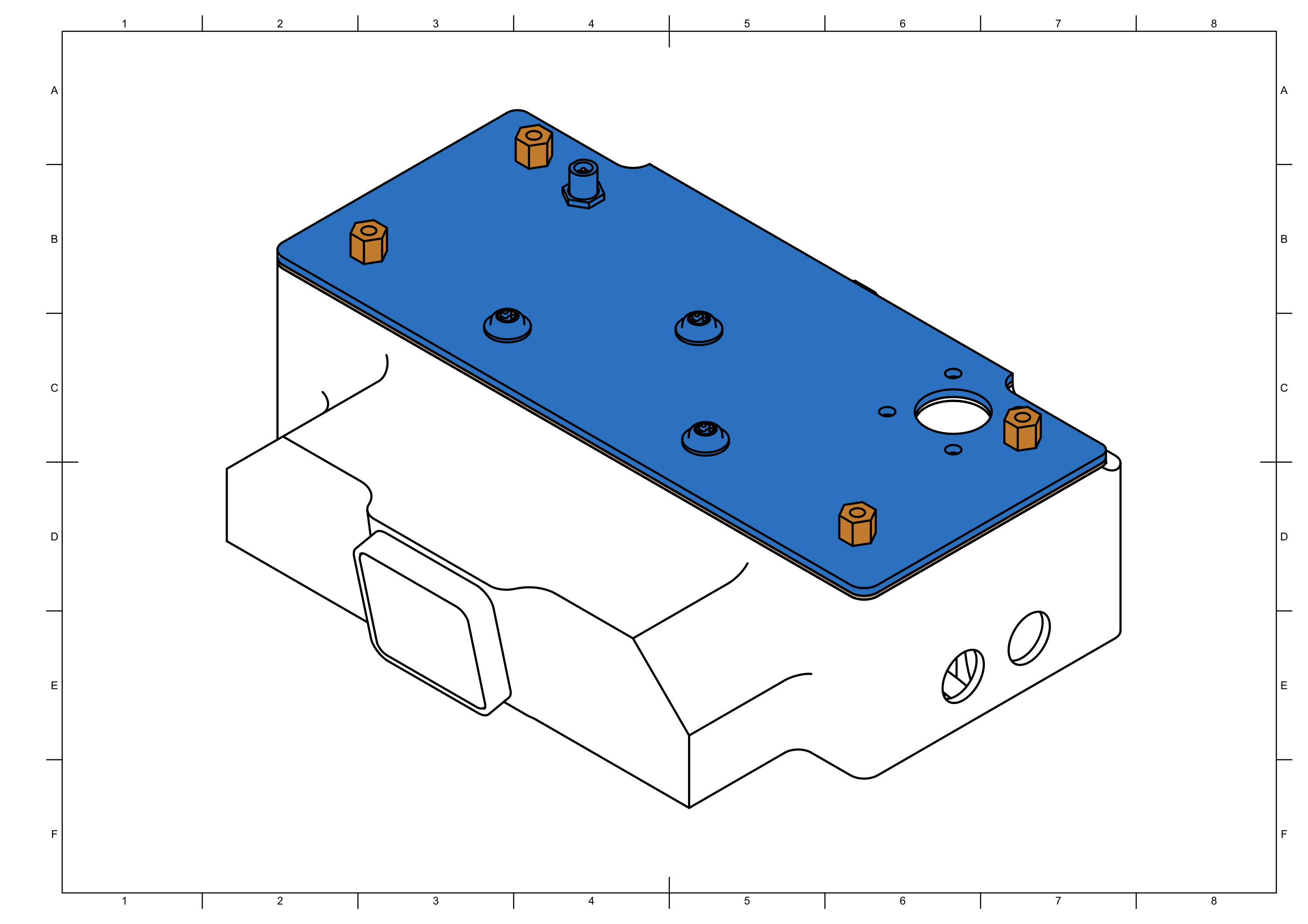
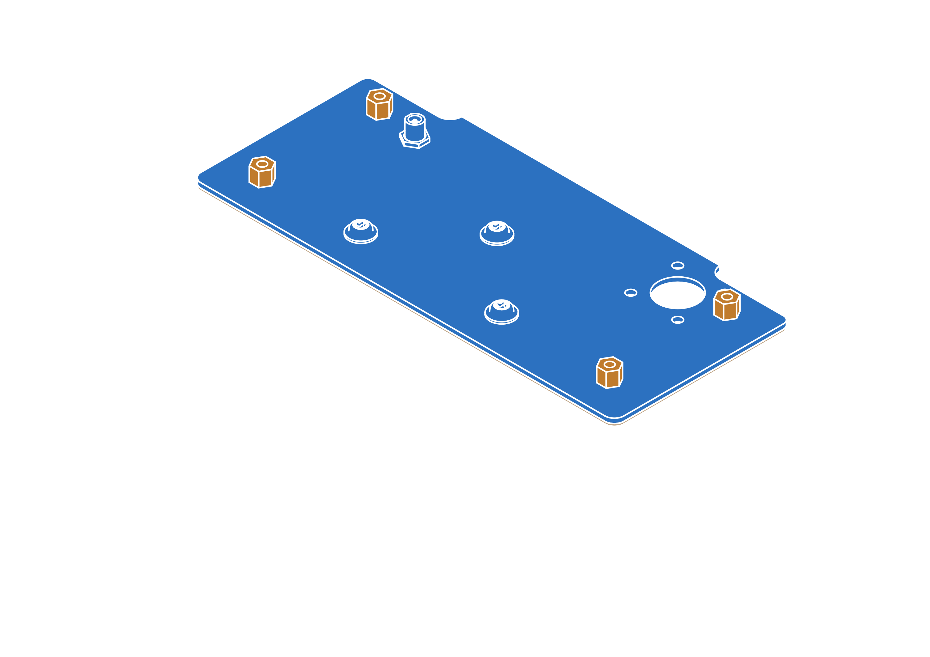
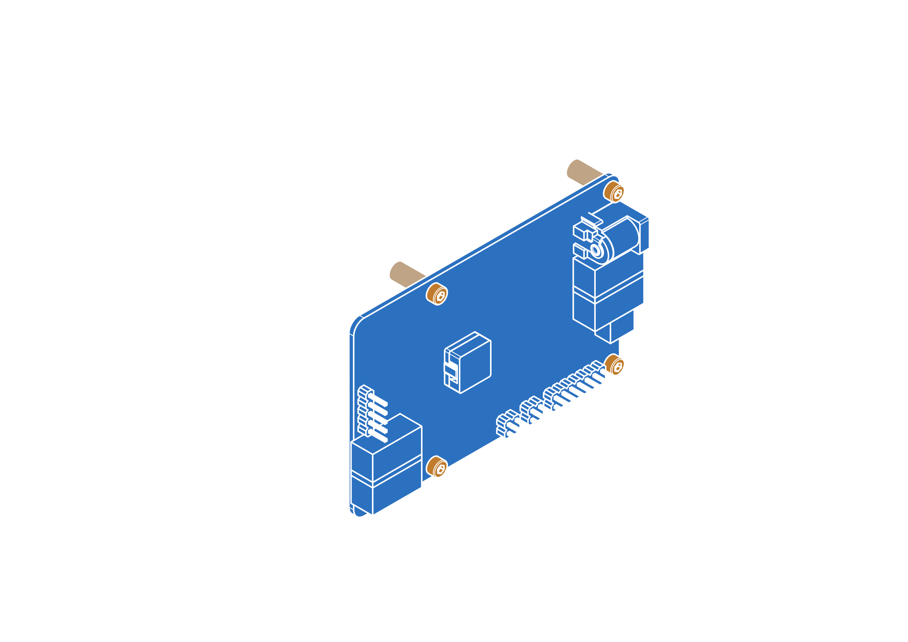
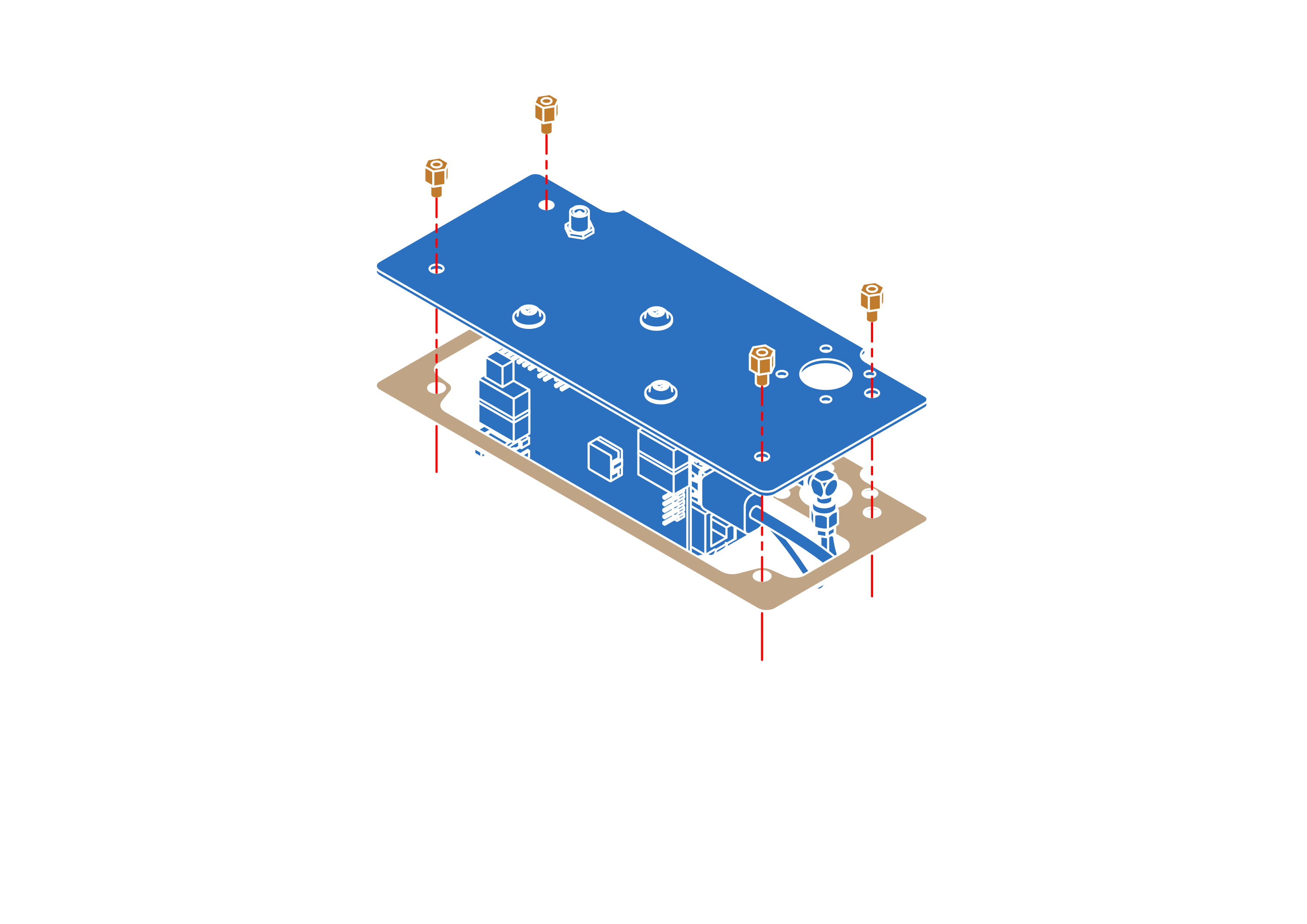
Step 15


Step 16
note
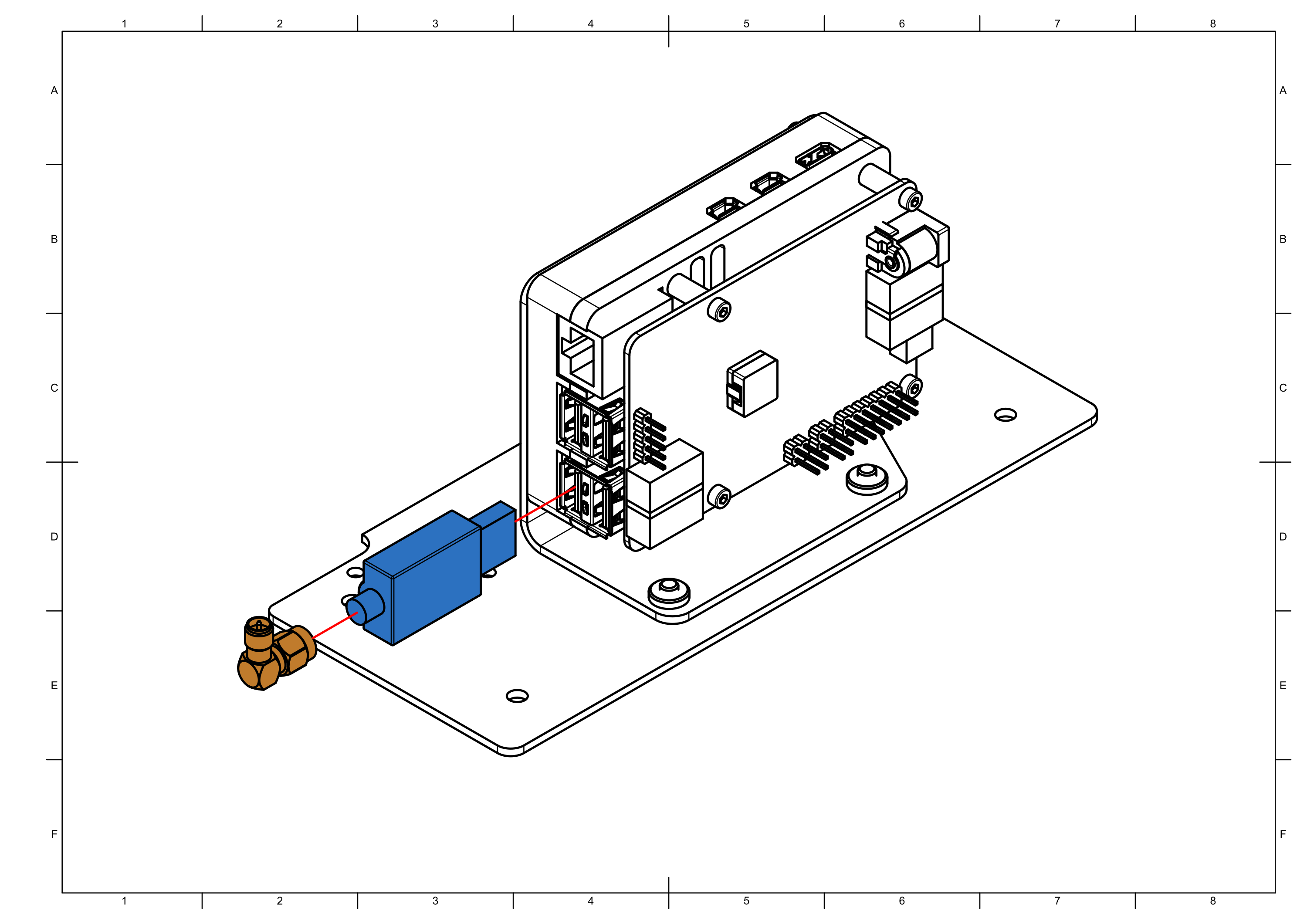
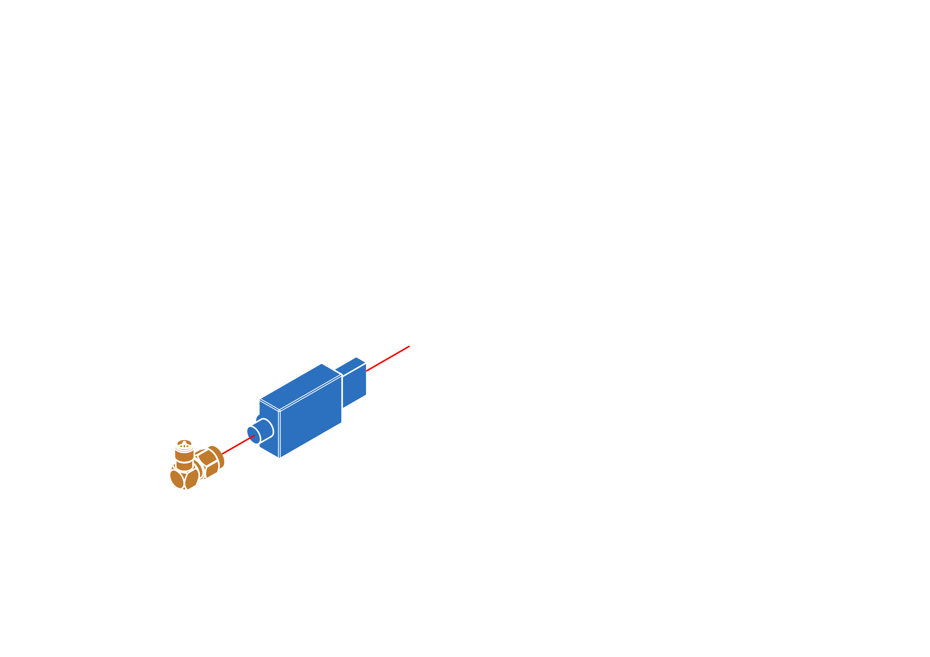
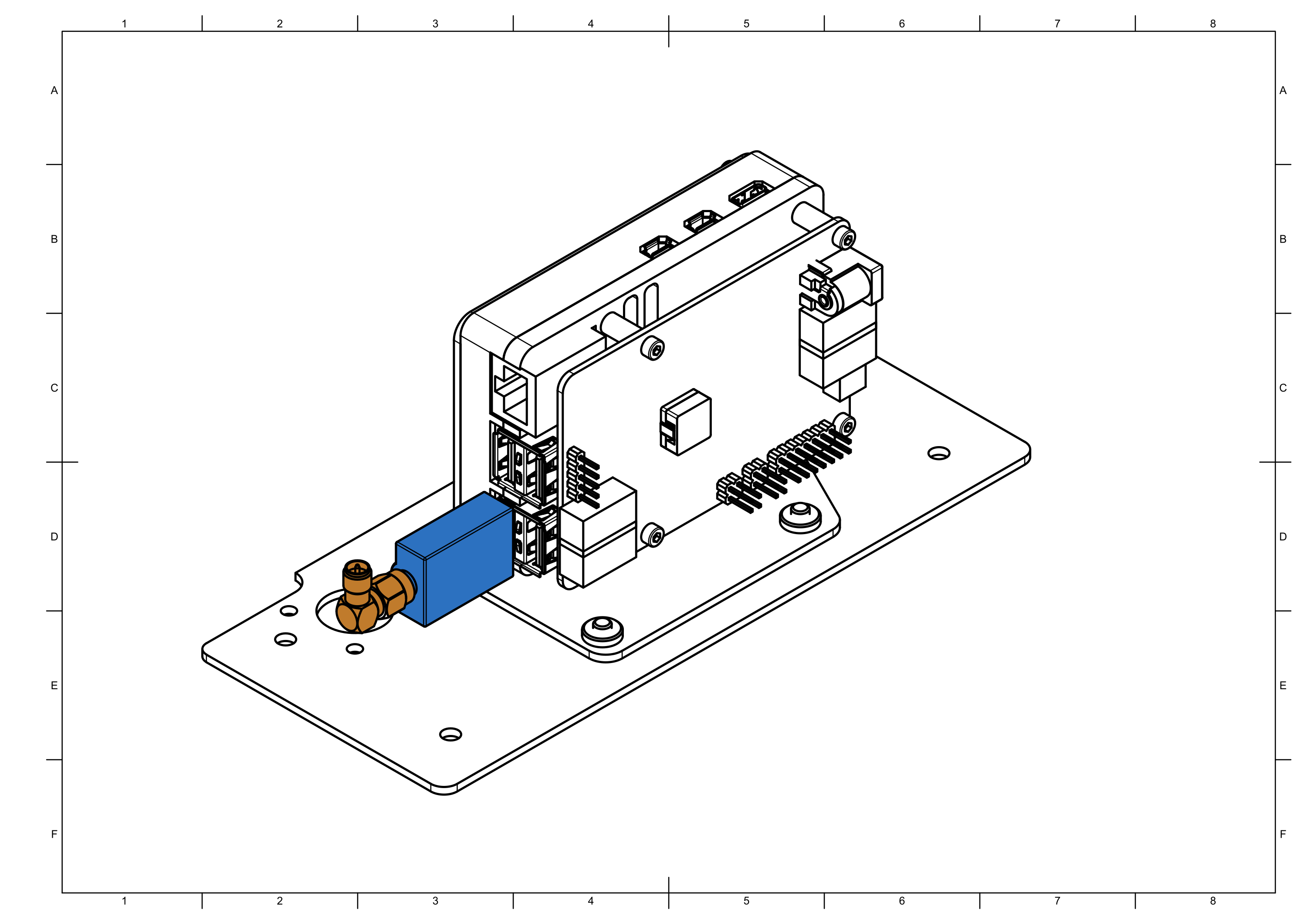
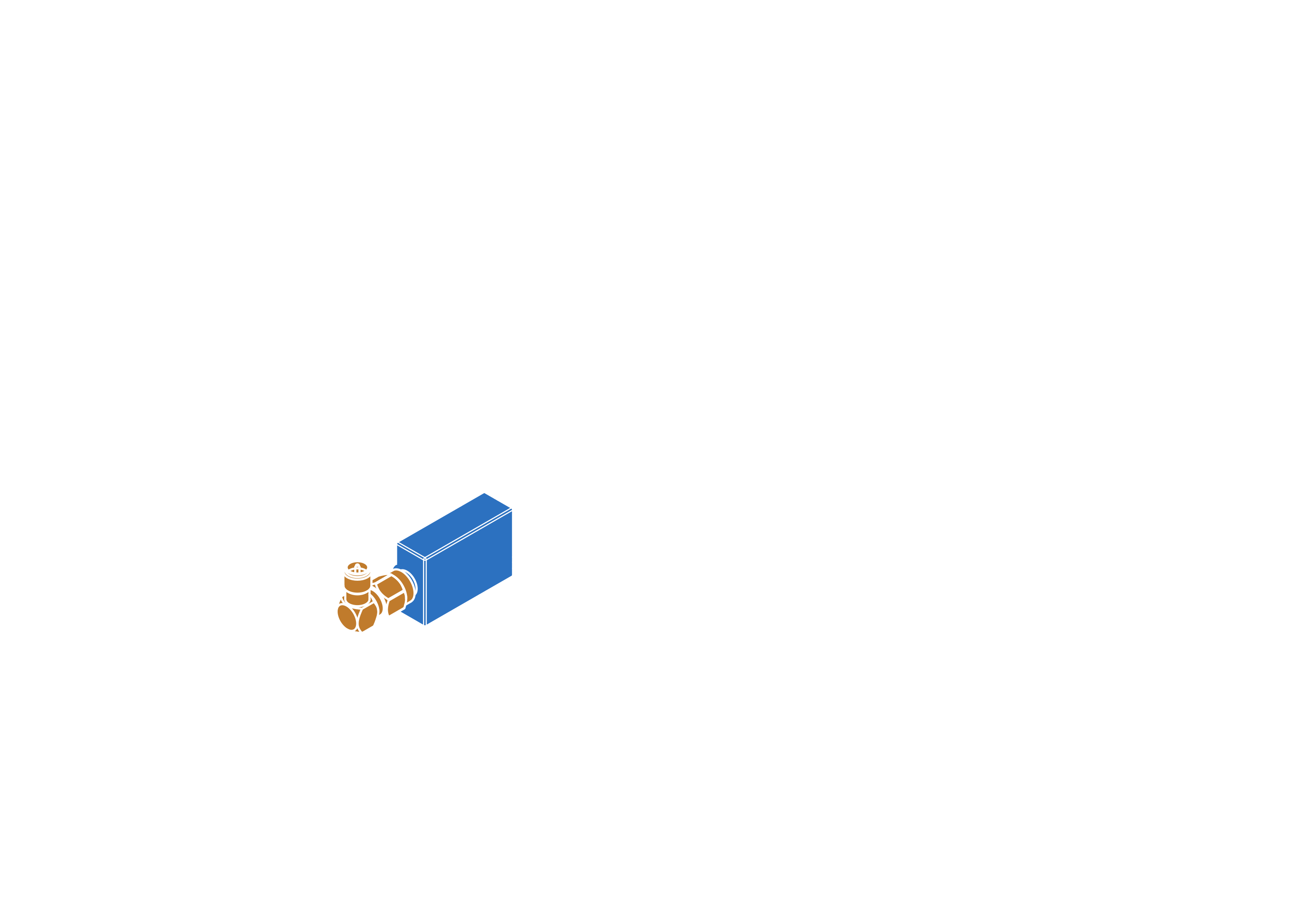
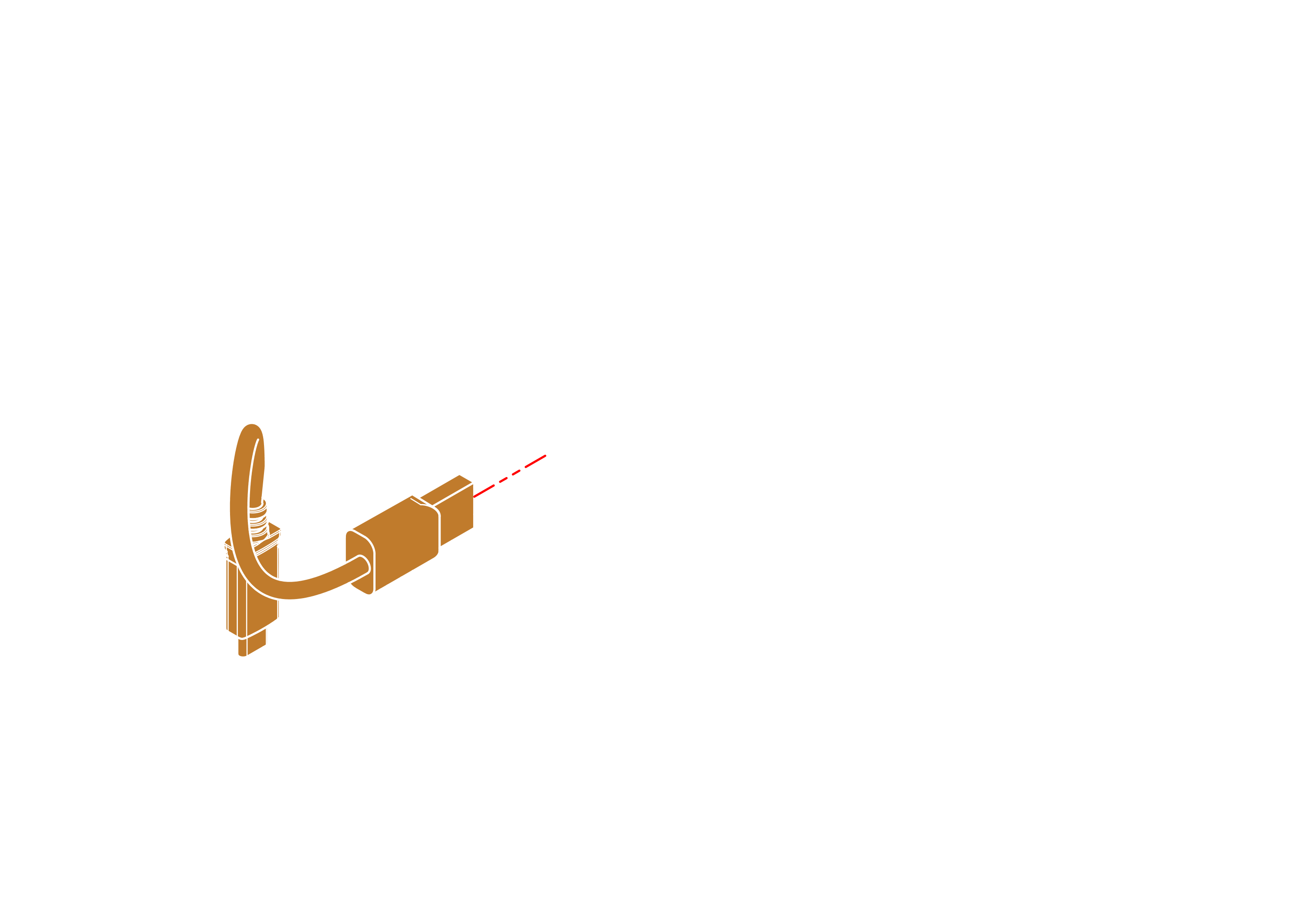
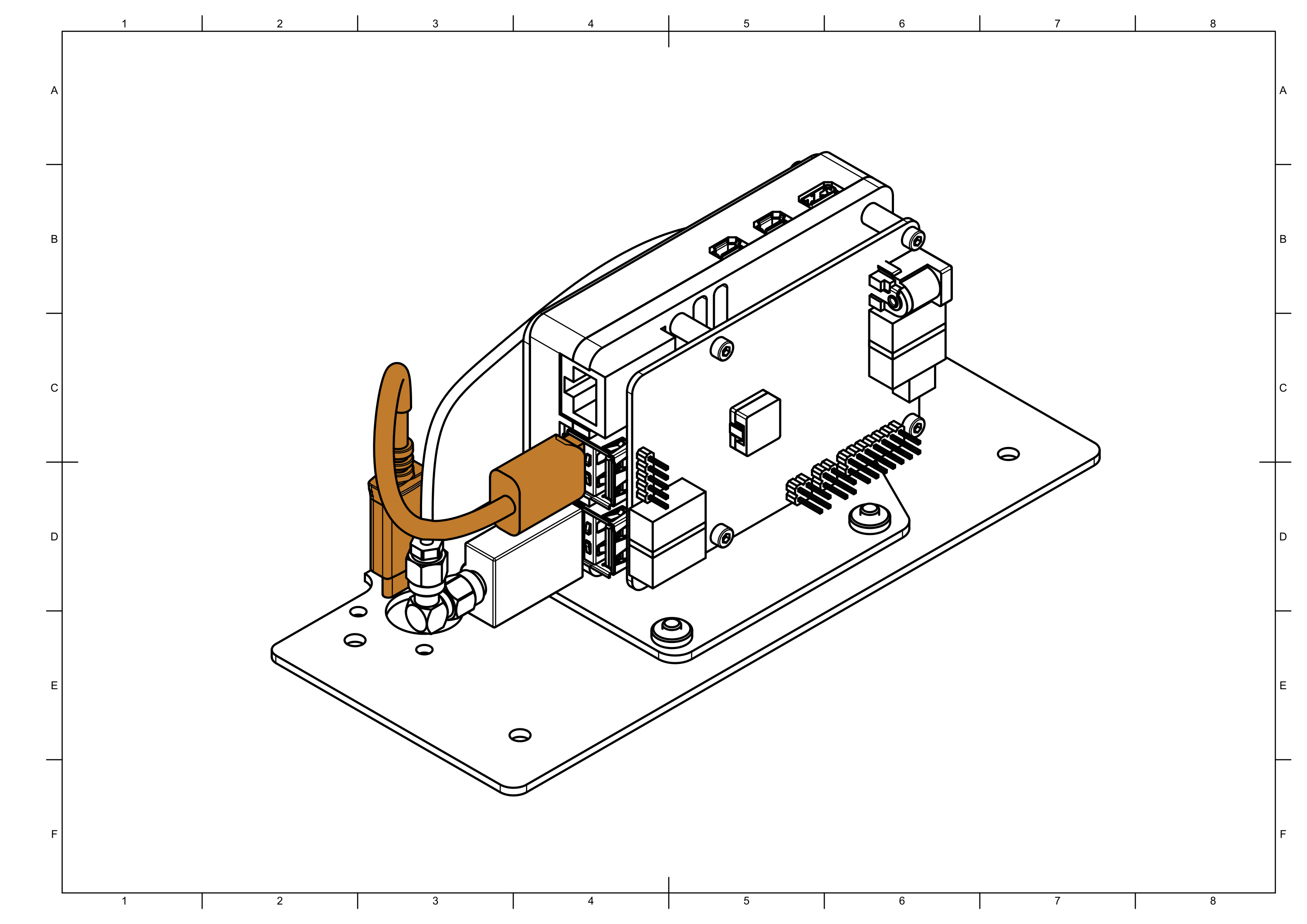
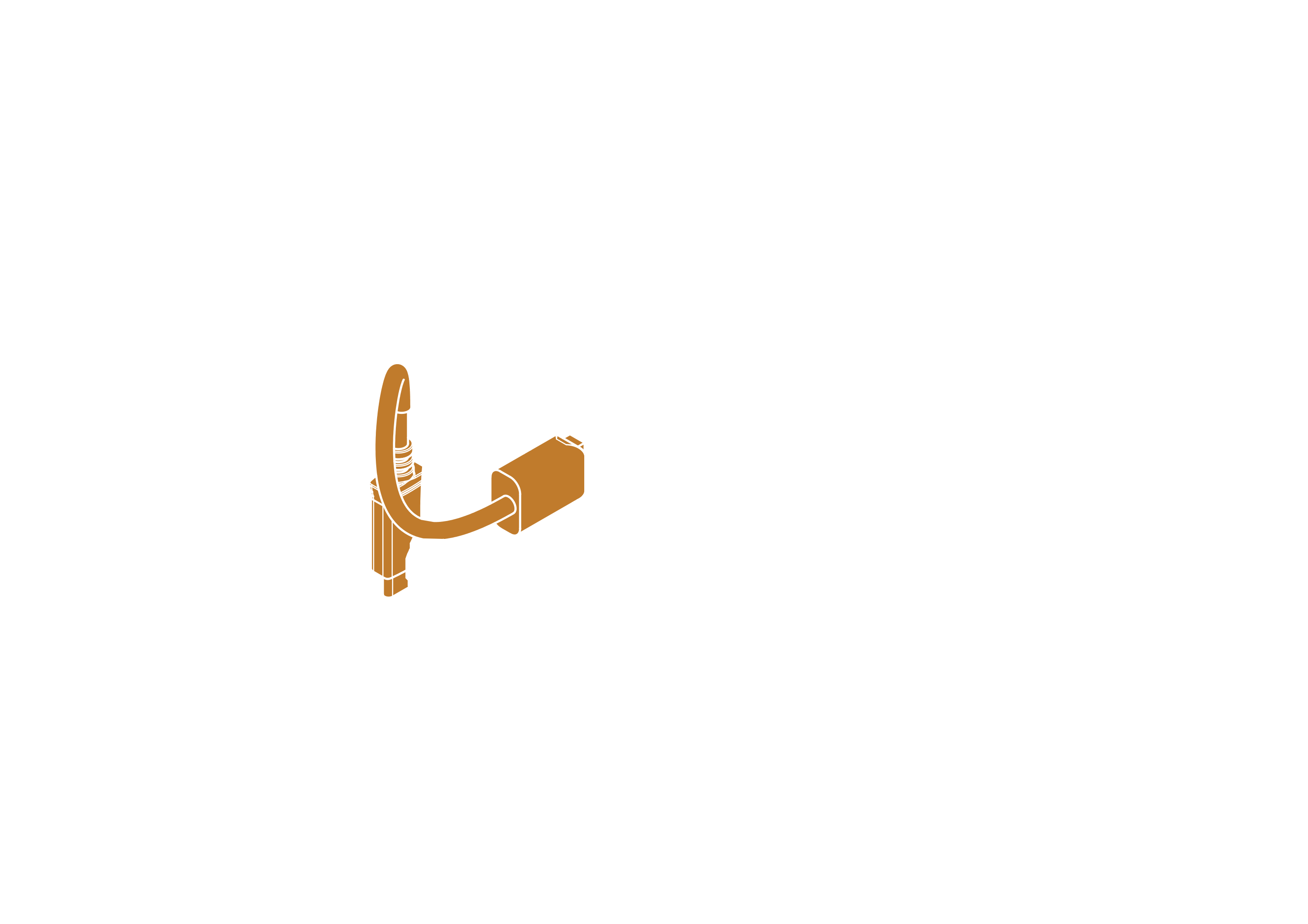
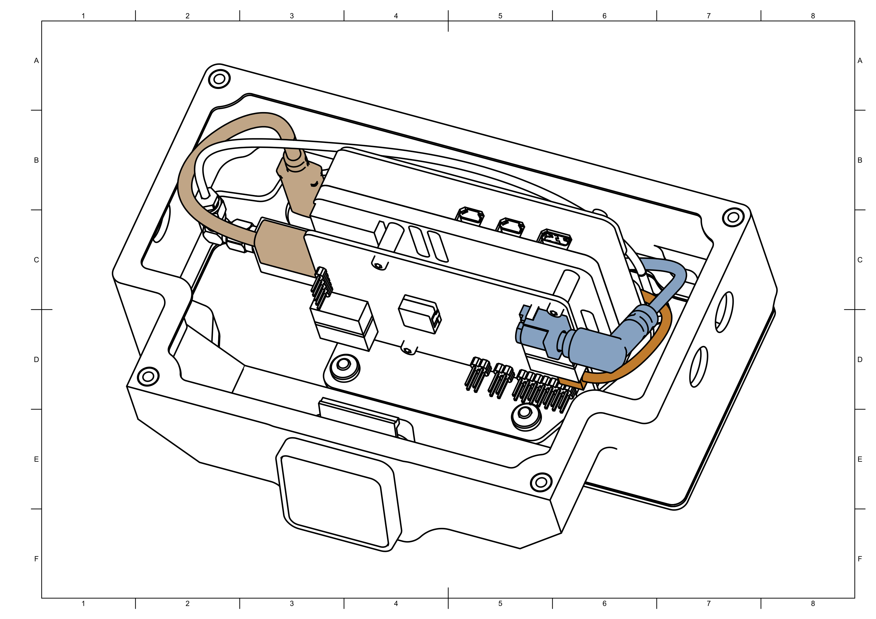
Connect power , LED and USB cables.
Make sure none of the cables are pinched between the box and its cover when box is closed in future step.
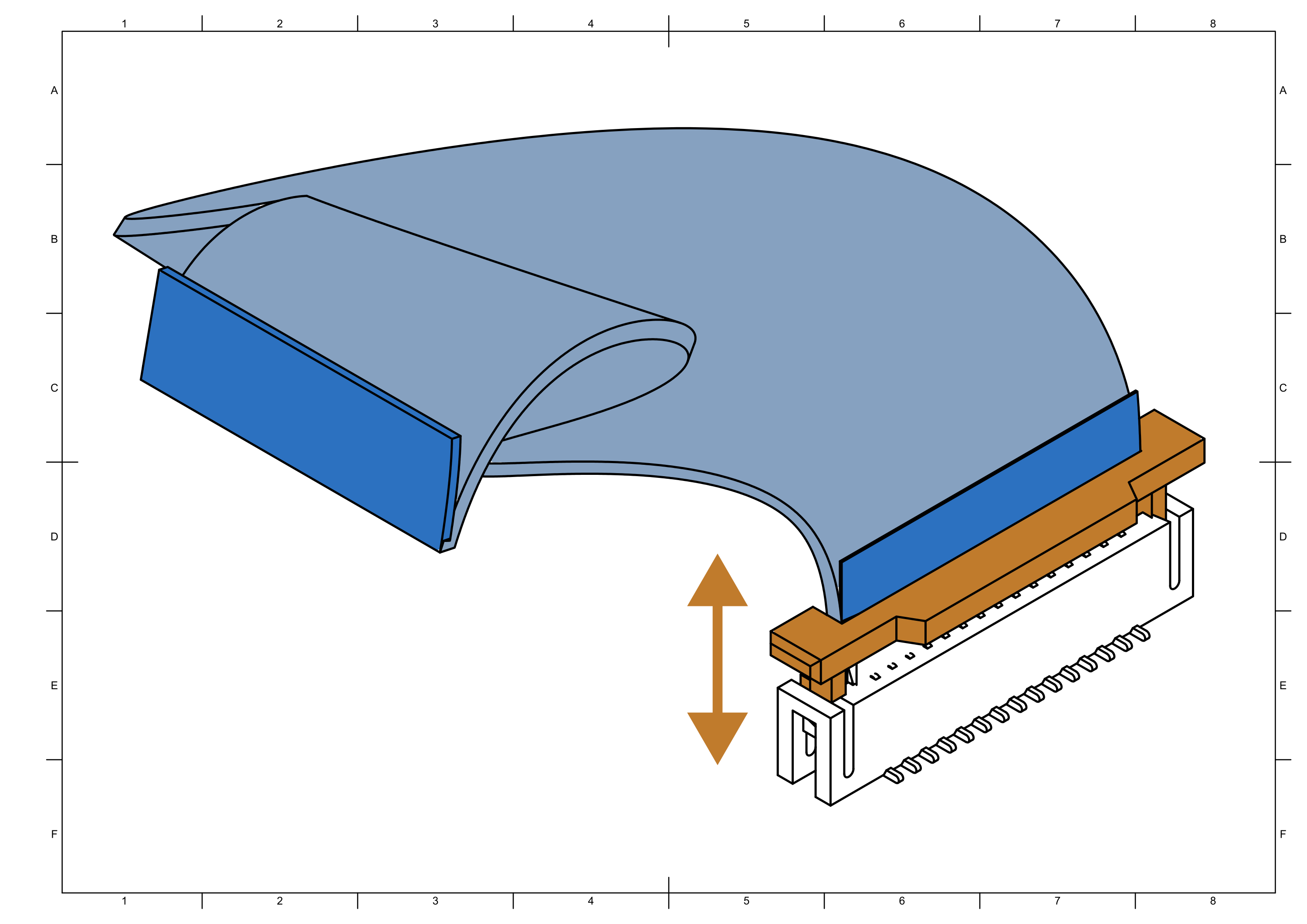
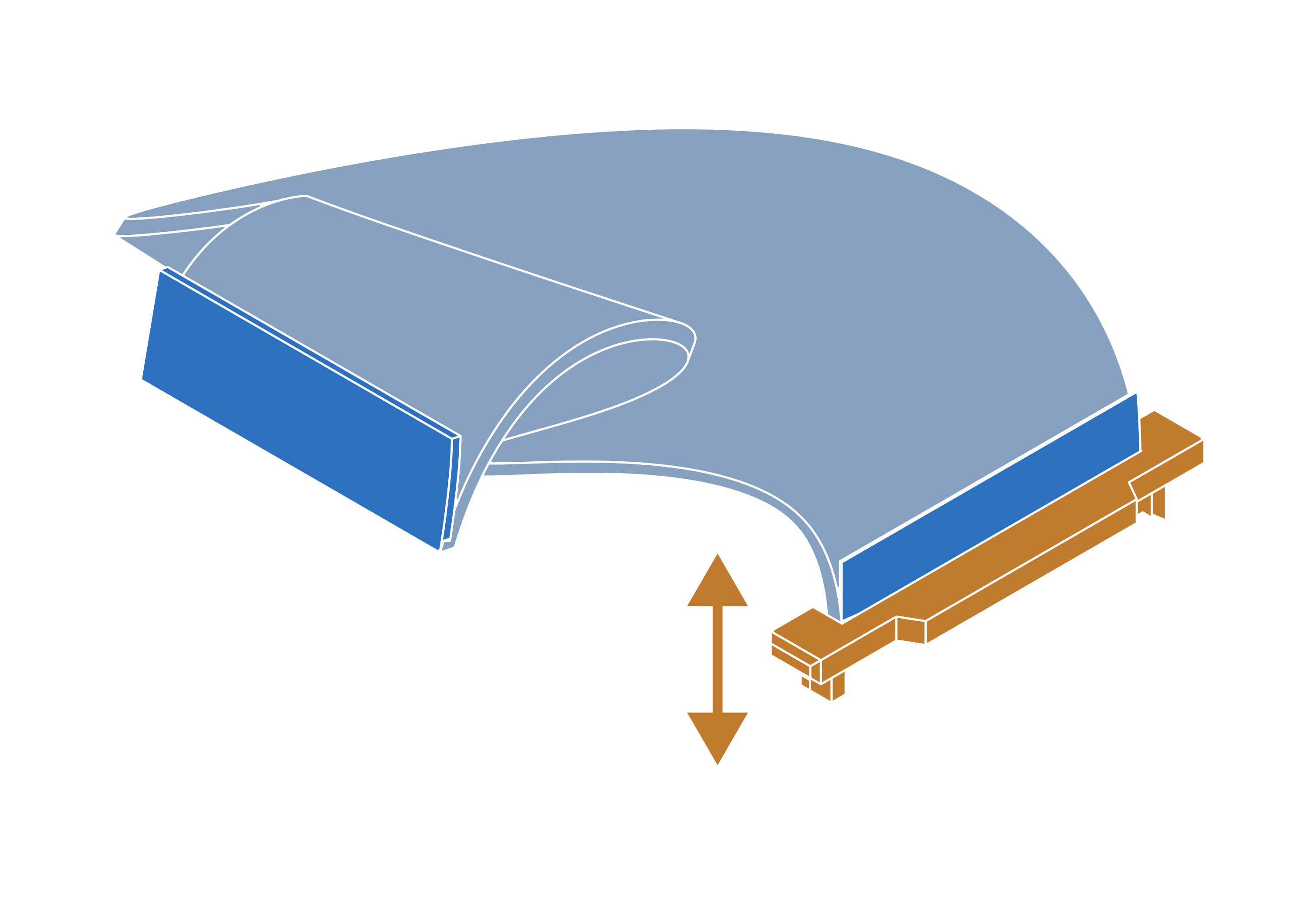
Step 17
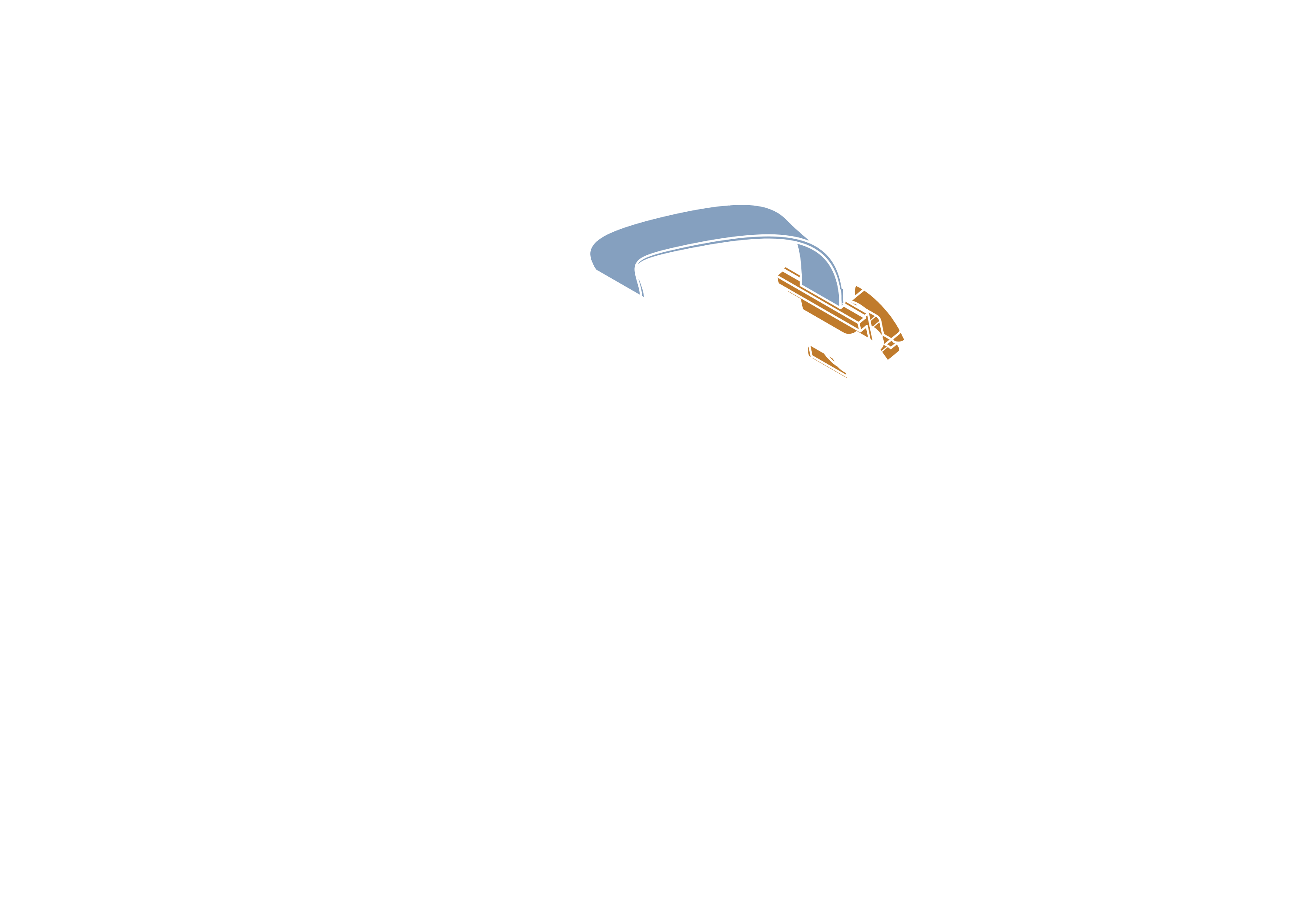
note
Make sure that camera ribbon is pushed all the way into the connector. Push down on connector handle to lock the ribbon in place.